MK Quilts | Handi Quilter Longarms | Pro-Stitcher | Quilting Classes | Quilt Finishing
  • Home
  • Support
  • MKQ University
  • Machine Sales
    • Request a Quote
    • HQ Machines Guide >
      • Moxie 15
      • Moxie XL 18
      • Amara 20
      • Forte/Amara 24
      • Infinity 26
      • Pro-Stitcher
      • Pro-Stitcher Lite
    • Extended Warranty
    • Self Installation
    • Used Machines
    • References
    • Your Testimonial
    • Refer-a-customer
    • ESP - Exceptional Service Program
  • Quilt Shop
    • Class Calendar
    • Past Classes & Events
  • Online Store
  • Longarm Quilting Services
  • MK Design Indexer
  • Quilts For Sale
  • Contact Us
  • About Us/Techs
  • Privacy Policy

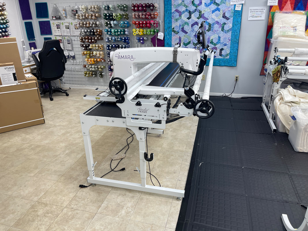
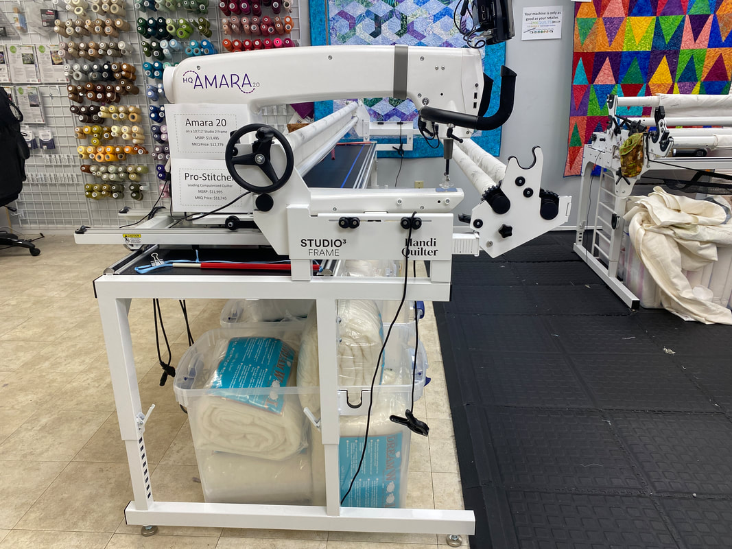
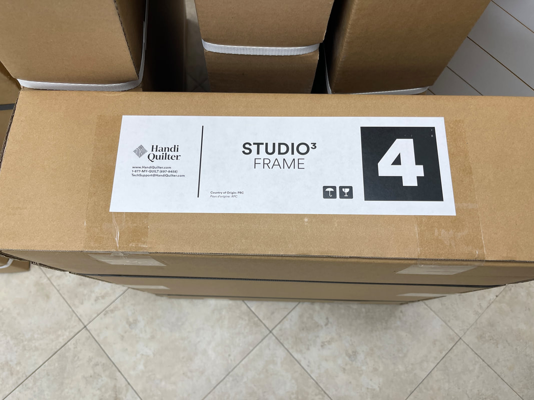
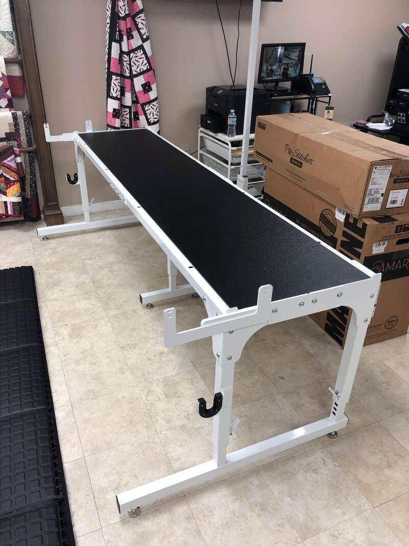
The new Studio3 frame

As of May 2023, Handi Quilter is no longer shipping the Studio2 frame.  The Studio2 added the adjustable sidearms to the original Studio frame which is an available upgrade to existing frames.  The Studio3 frame has several MAJOR changes that make some accessories like the extra hand wheels and the Secret Drawers incompatible with the Studio2 versions.
The 'Picture Book' below showing the Studio2 installation still provides many details that can be helpful when setting up the Studio2 or Gallery2 frames.  This section will attempt to identify some of the differences and try to clarify issues that lead arose during our first experience with the installation process.
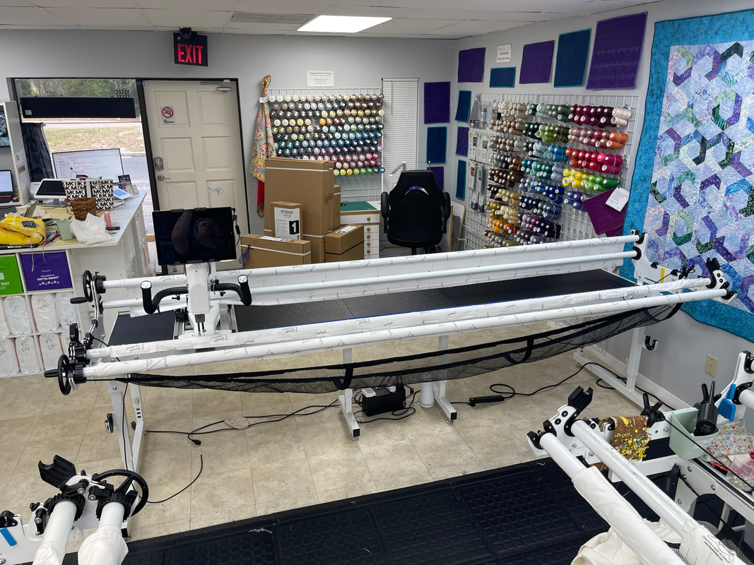
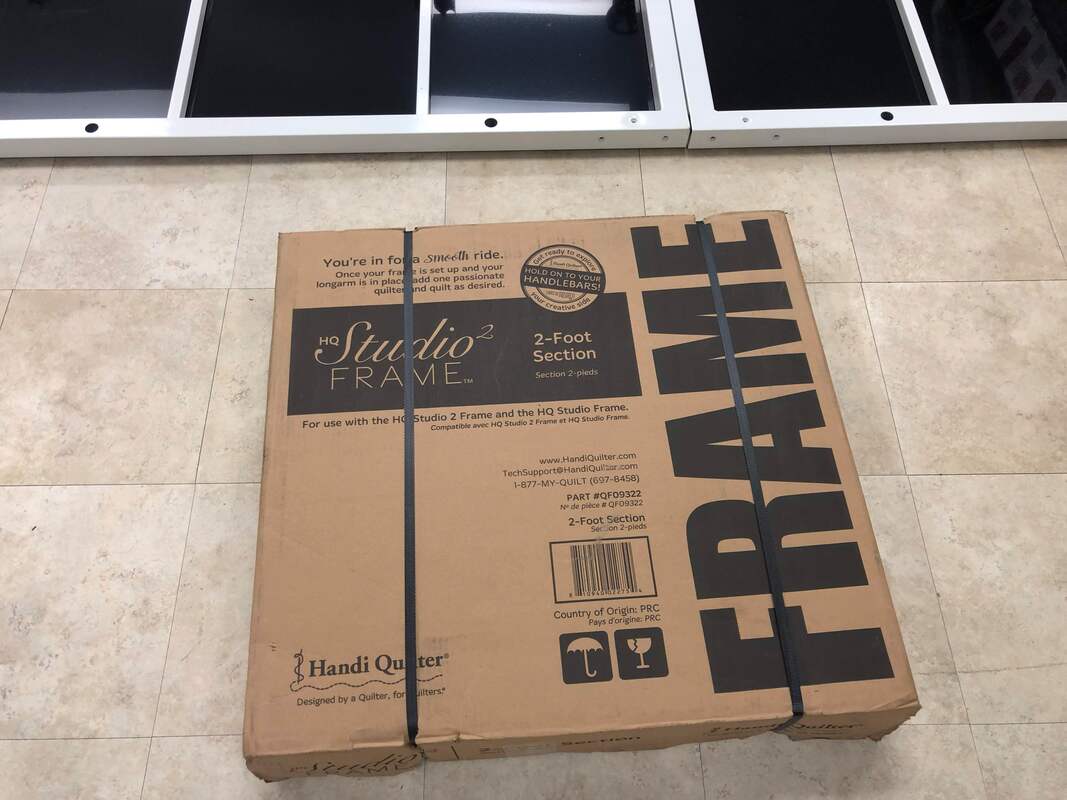
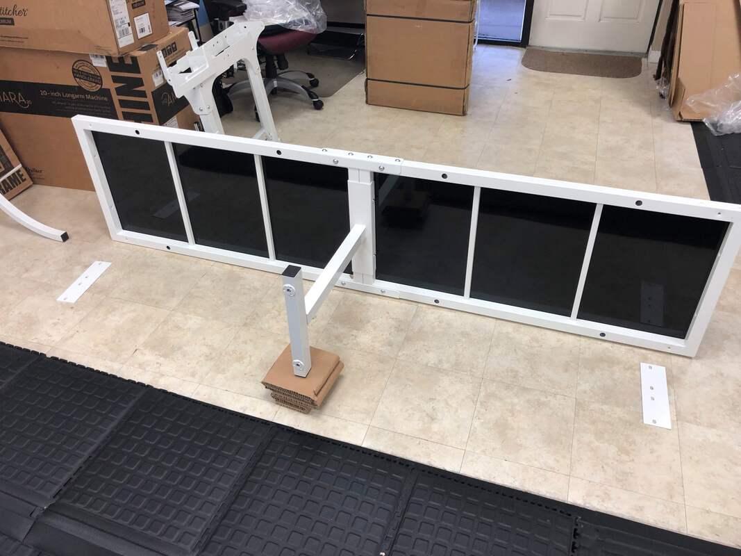
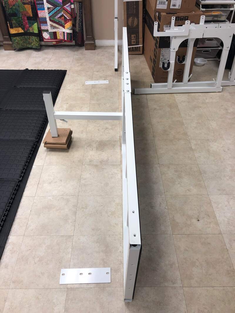
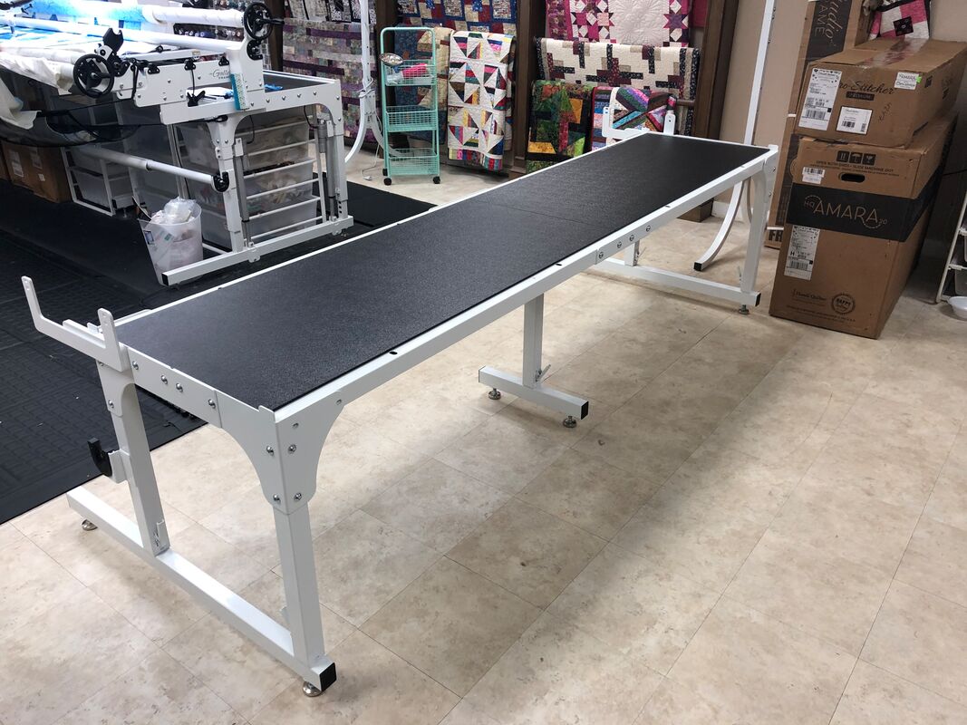
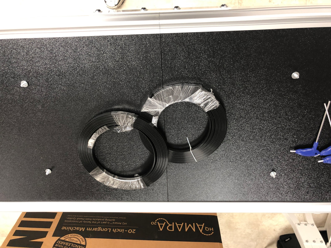
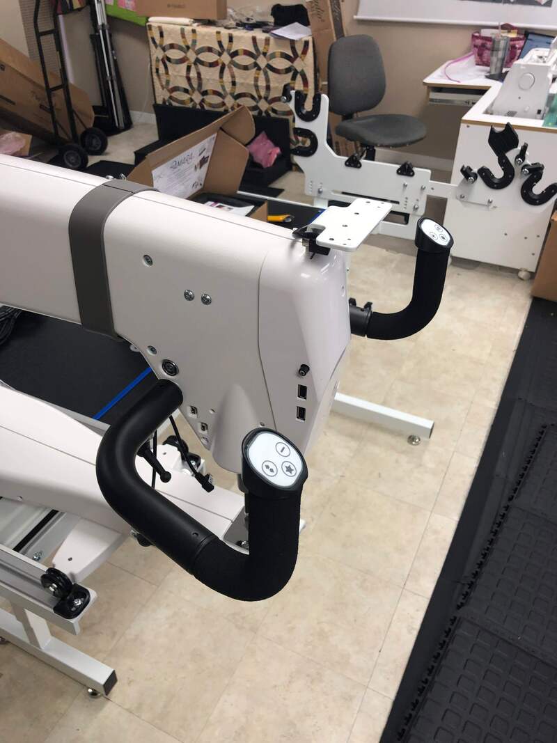
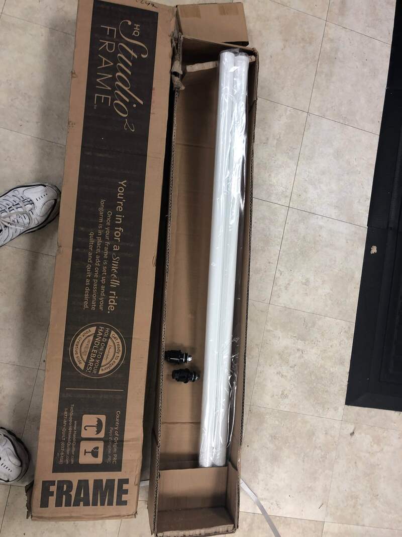
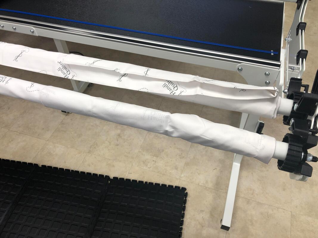
The original Studio2 frame
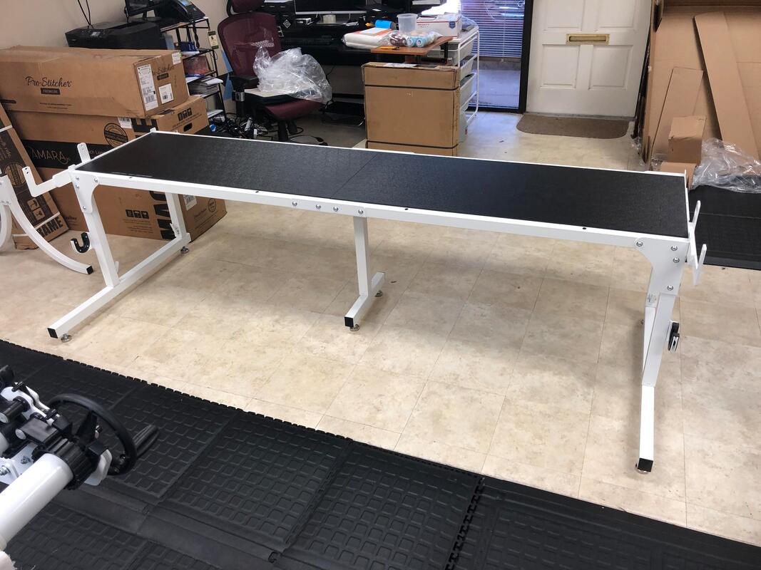
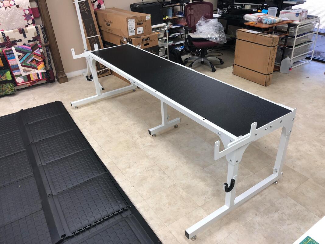
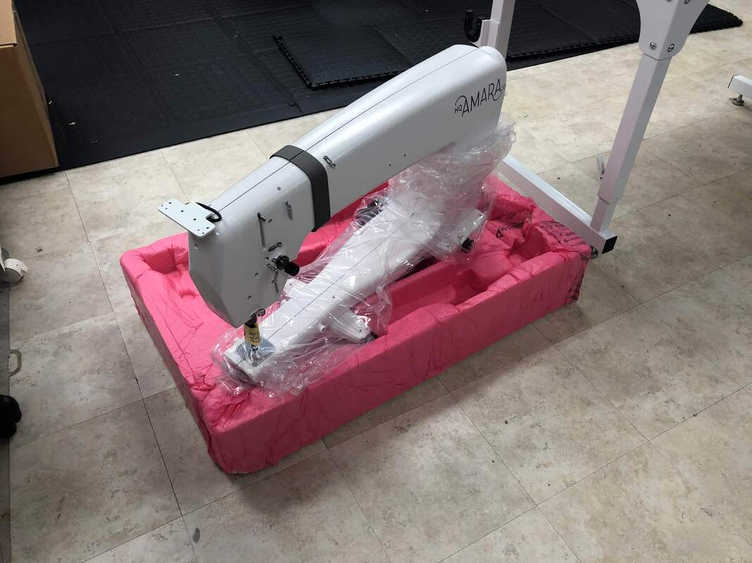
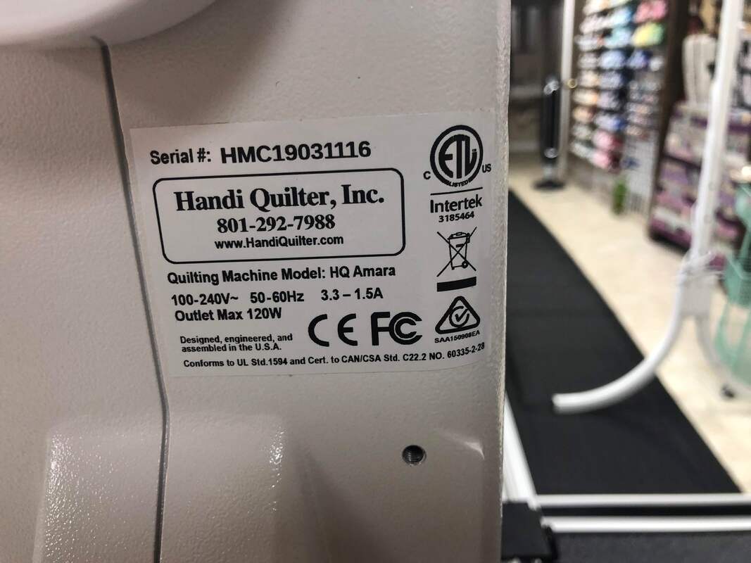
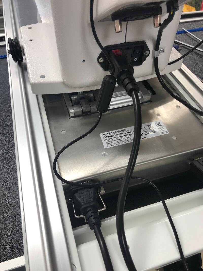
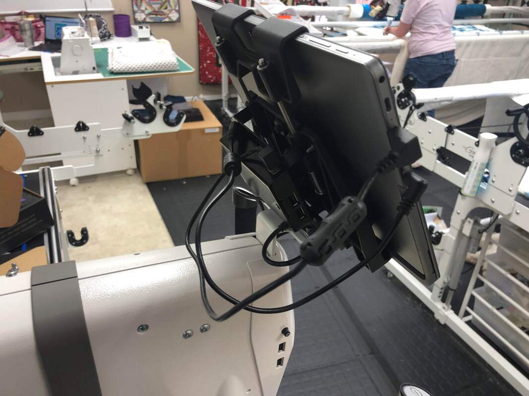
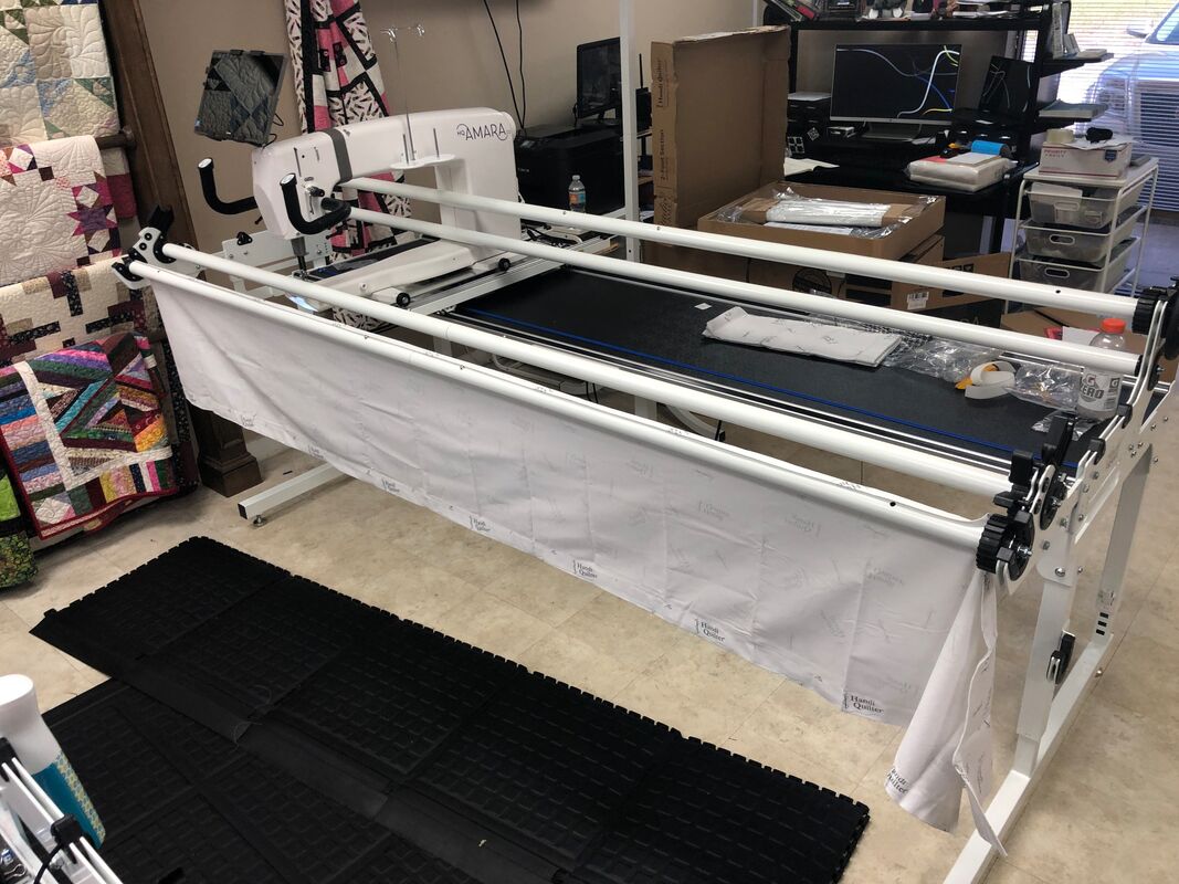
We swapped out our shop Studio2 frame that was set up at 10ft with Pro-Stitcher and an Amara20.  You may want to refer back to these photos when we talk about the differences.  We will also share some perspective on why some of the changes (may) have been made.
Picture
Picture
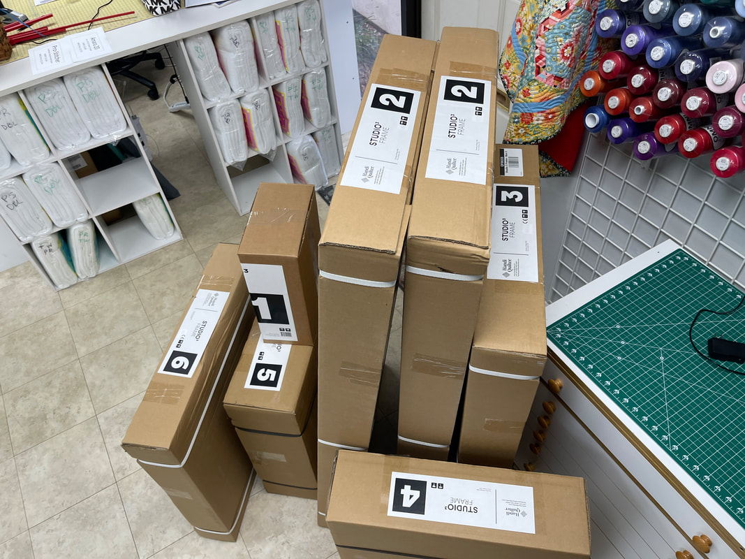
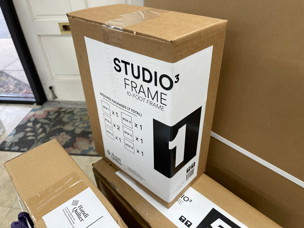
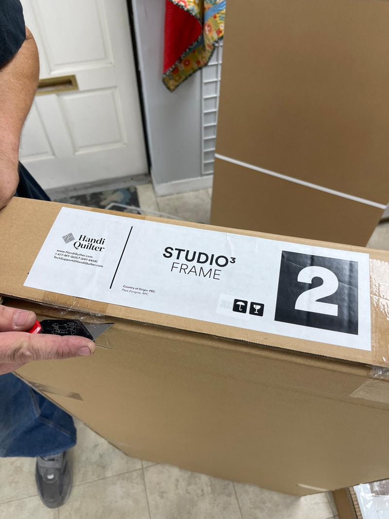
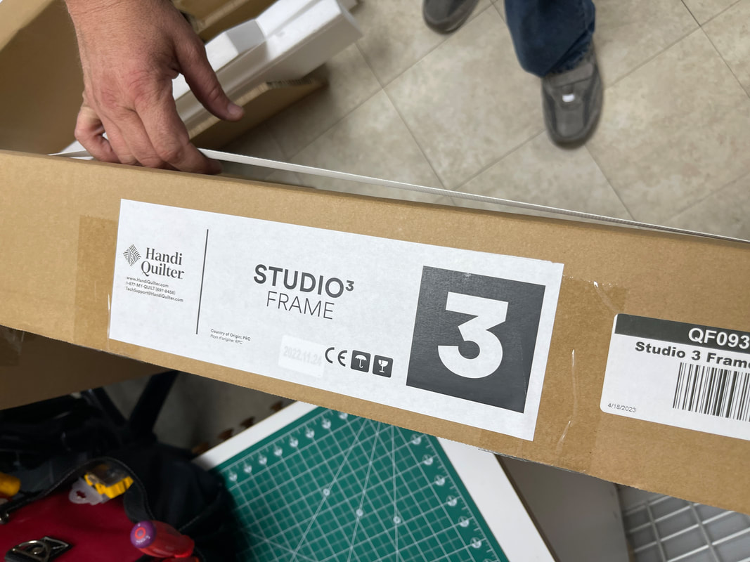
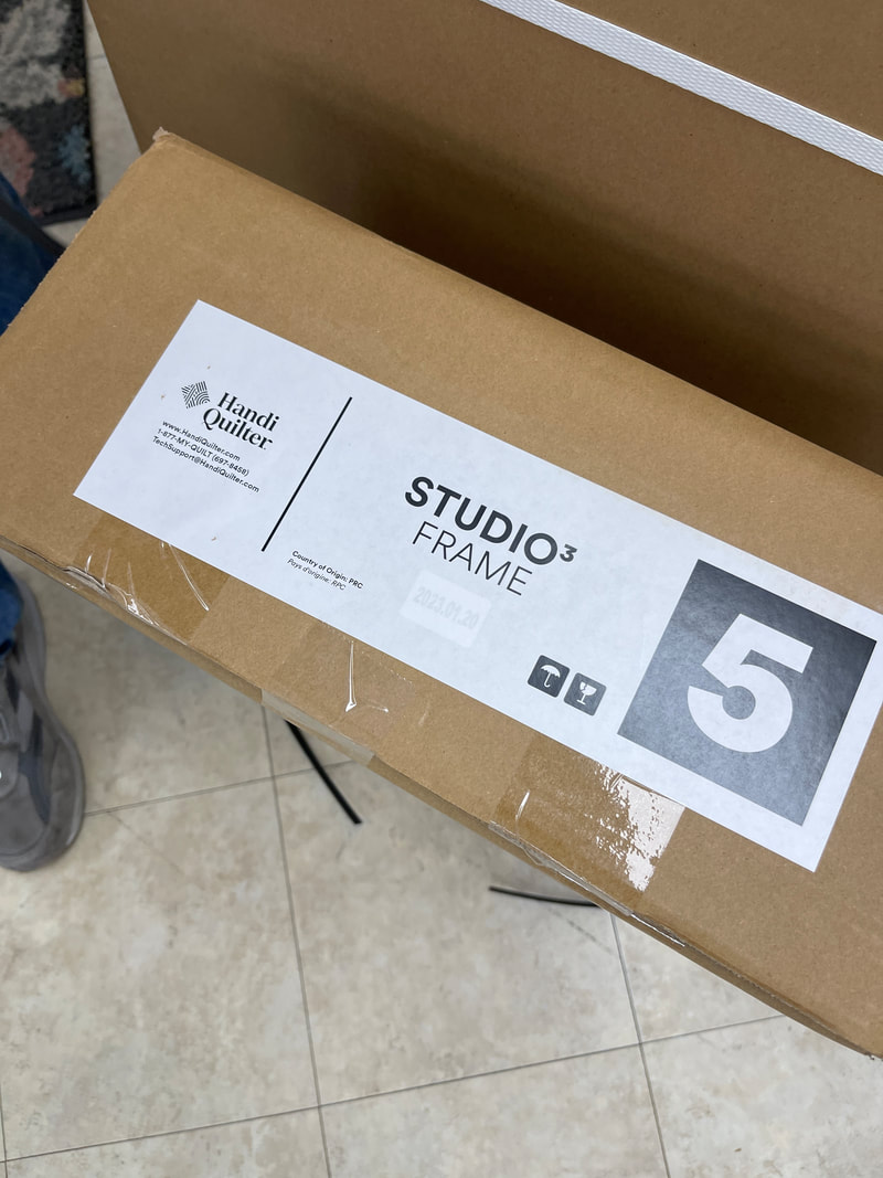
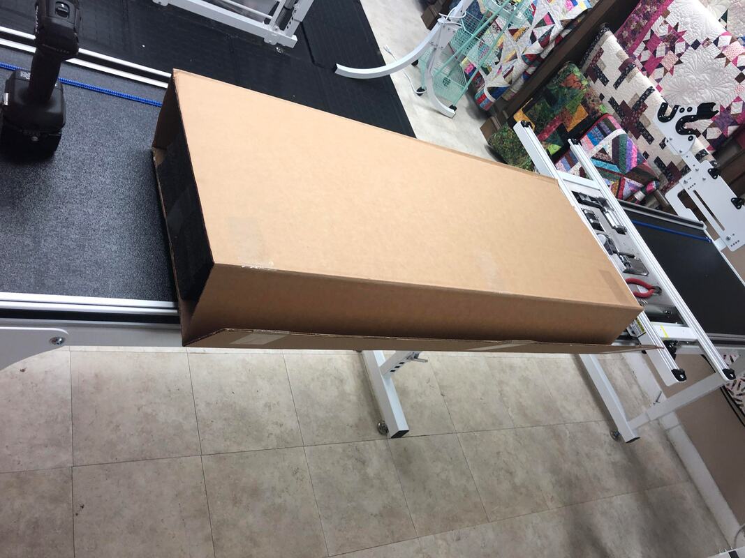
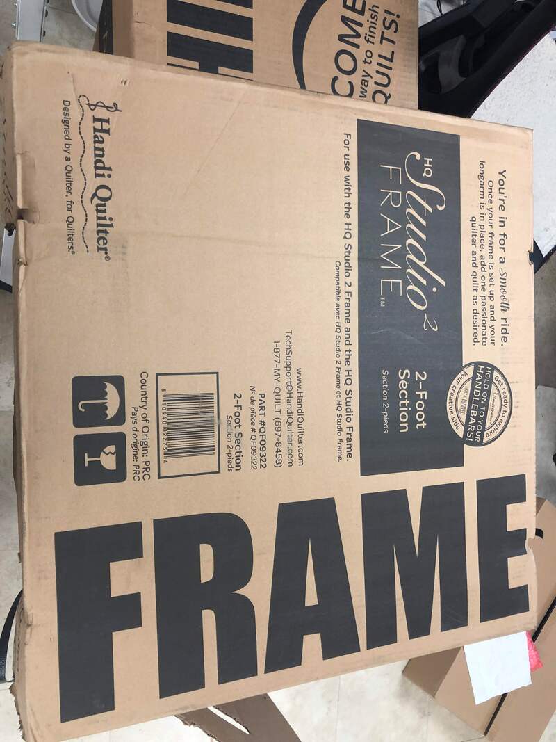
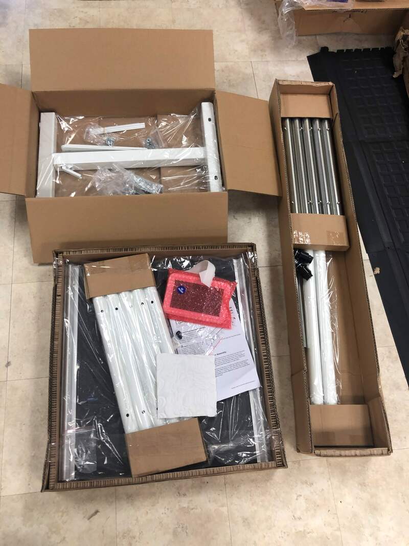
Meet the new Studio3 frame - More Boxes
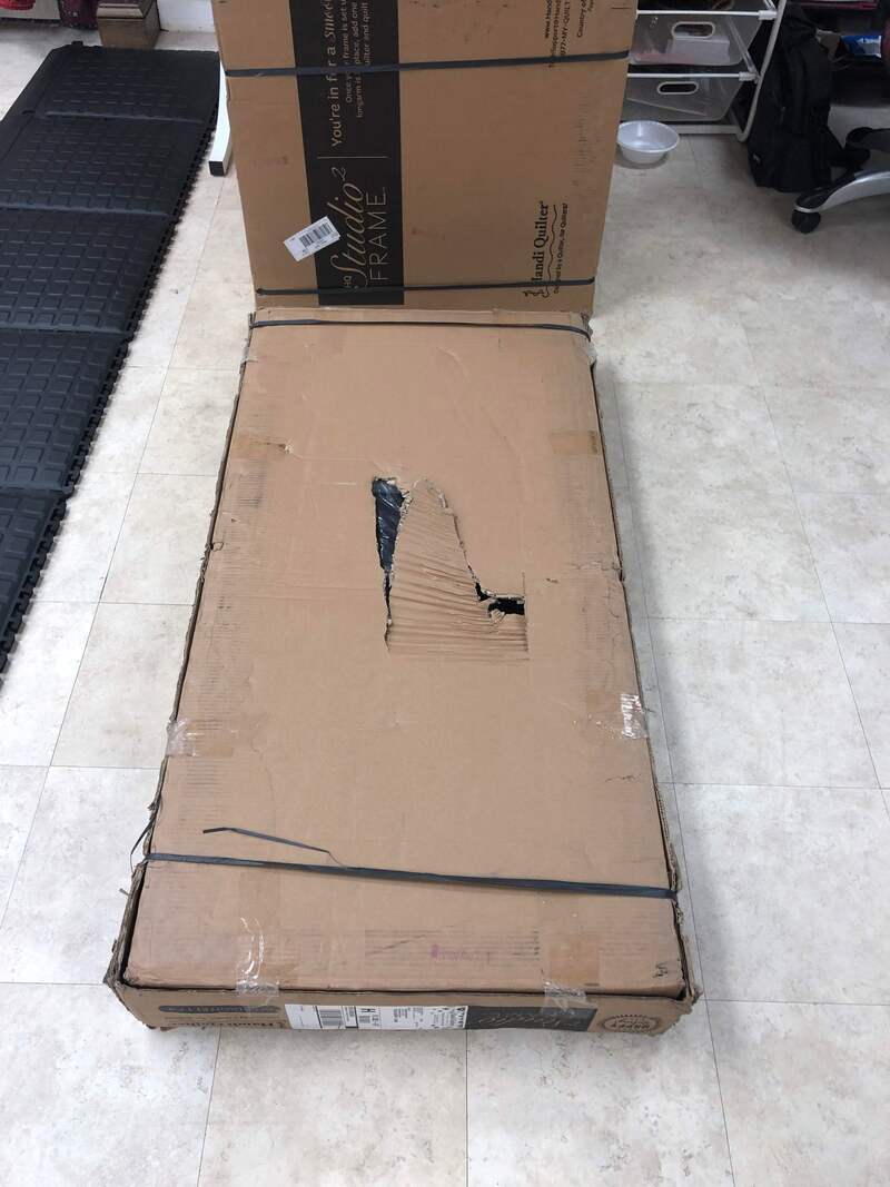
This may not seem important.  However, one of the most challenging issues we have had since the Covid years has been with shipping the Studio2 frame.  Many of the boxes exceeded 50 pounds and would be damaged in route to the customer.
This is the 10ft configuration.  The 12ft configuration will have a different Box 1 and likely include a third #2 box and not include the #6 box.  This will make more sense as you see it unboxed.
Picture
Picture
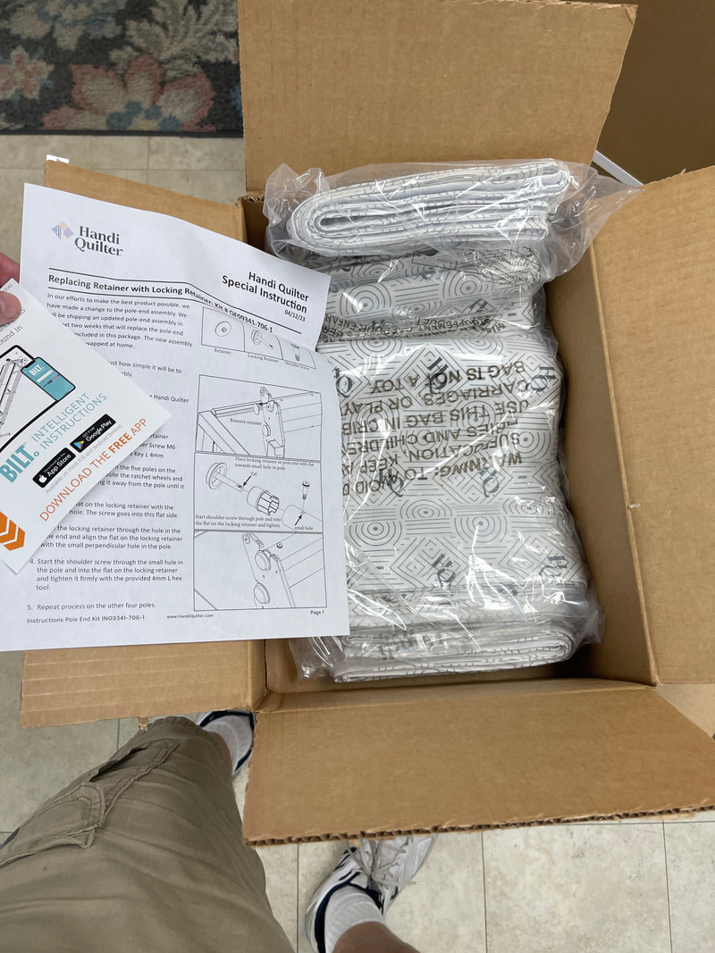
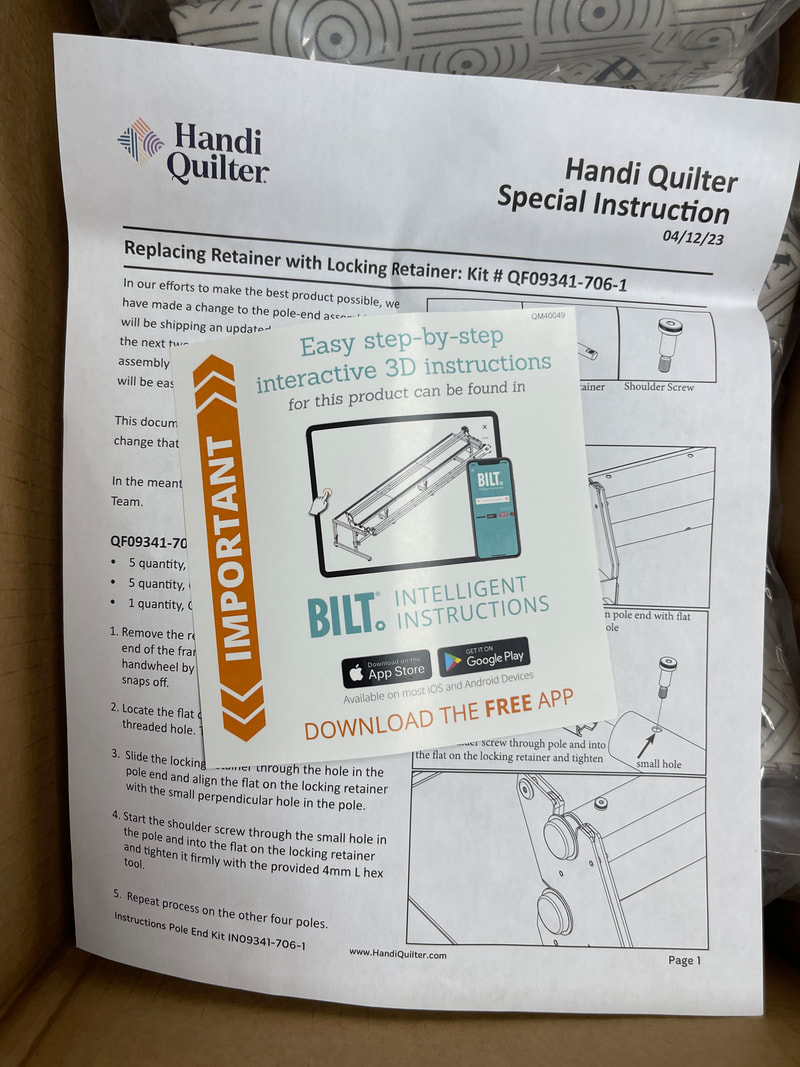
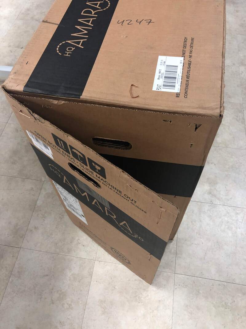
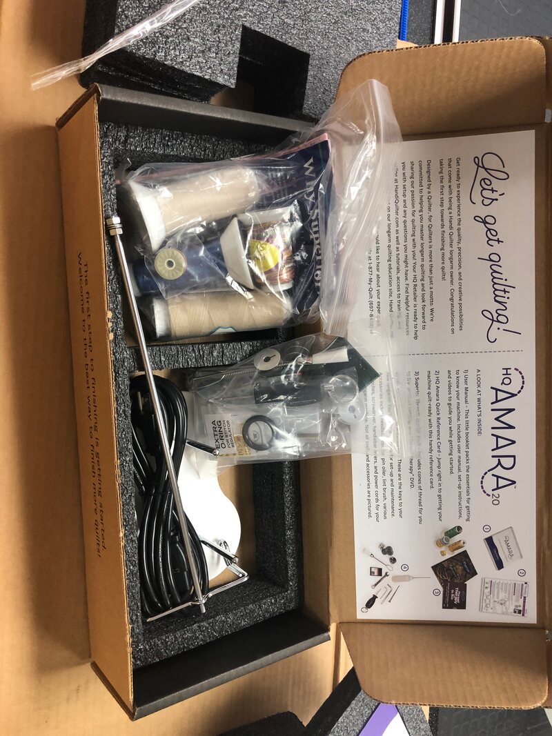
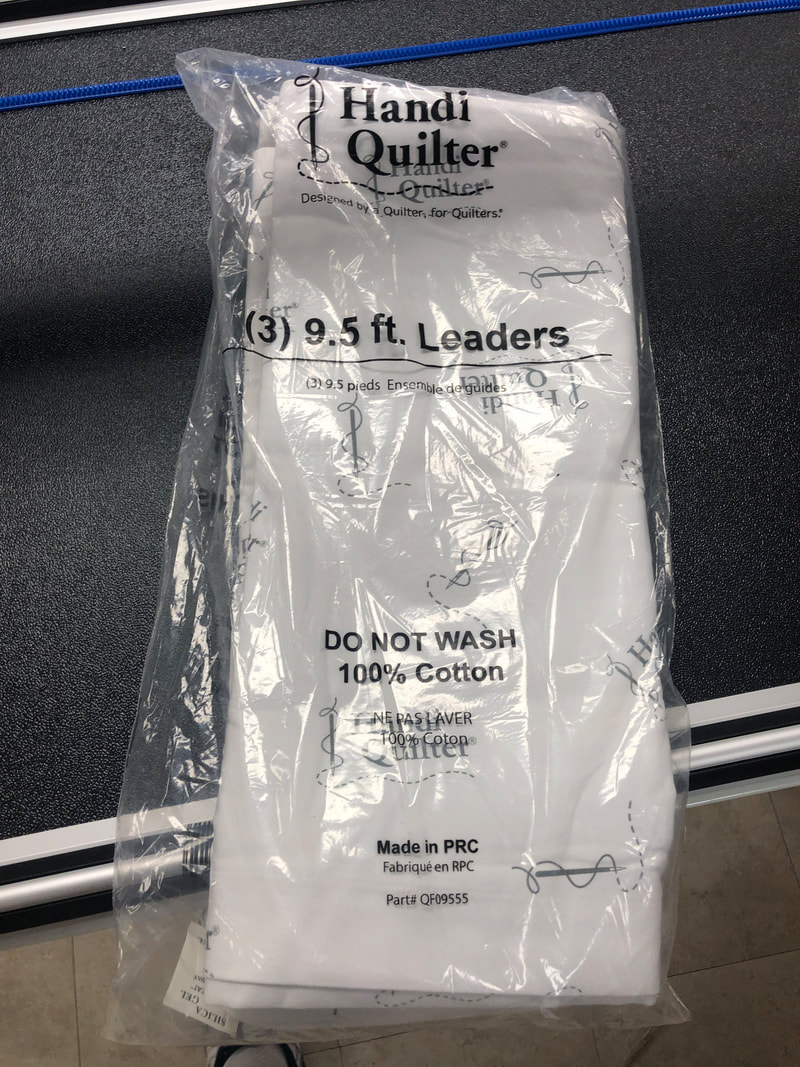
BOX 1: Leaders and notices
The Studio3 now comes with newly branded leaders and INCLUDES A SUPER LEADER!

The box currently includes a notice about a pending enhancement to the ends of the poles.  These parts were NOT included in this shipment and will be coming later.
Picture
Picture
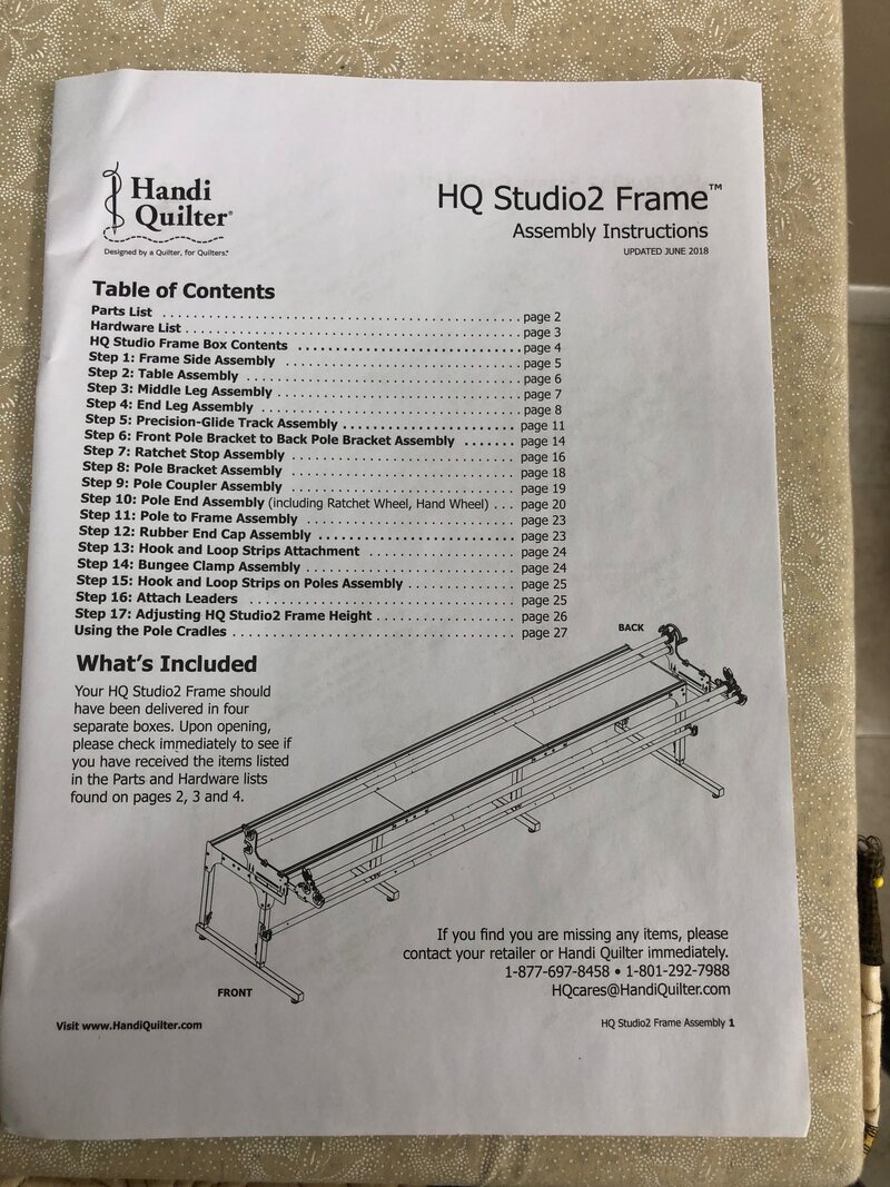
Installation Instructions:  The BILT App
If you have a smart phone or tablet running AndroidOS or AppleOS, you can download the app and access the installation instructions in animated format.  We used both the animated BILT and the written instructions and still got a few things wrong.

The written instruction manual is available in BOX 4.
Picture
Picture
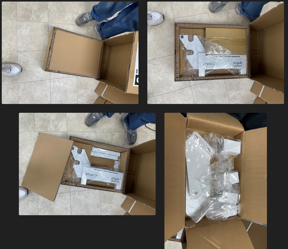
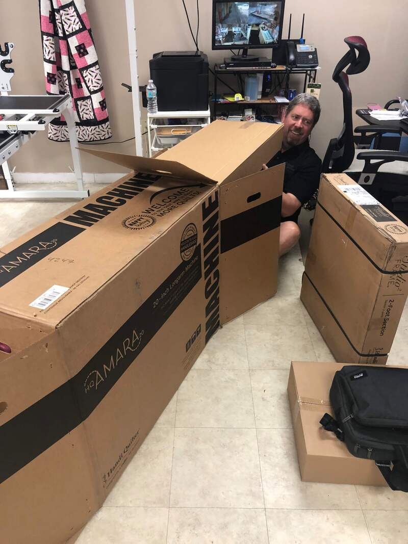
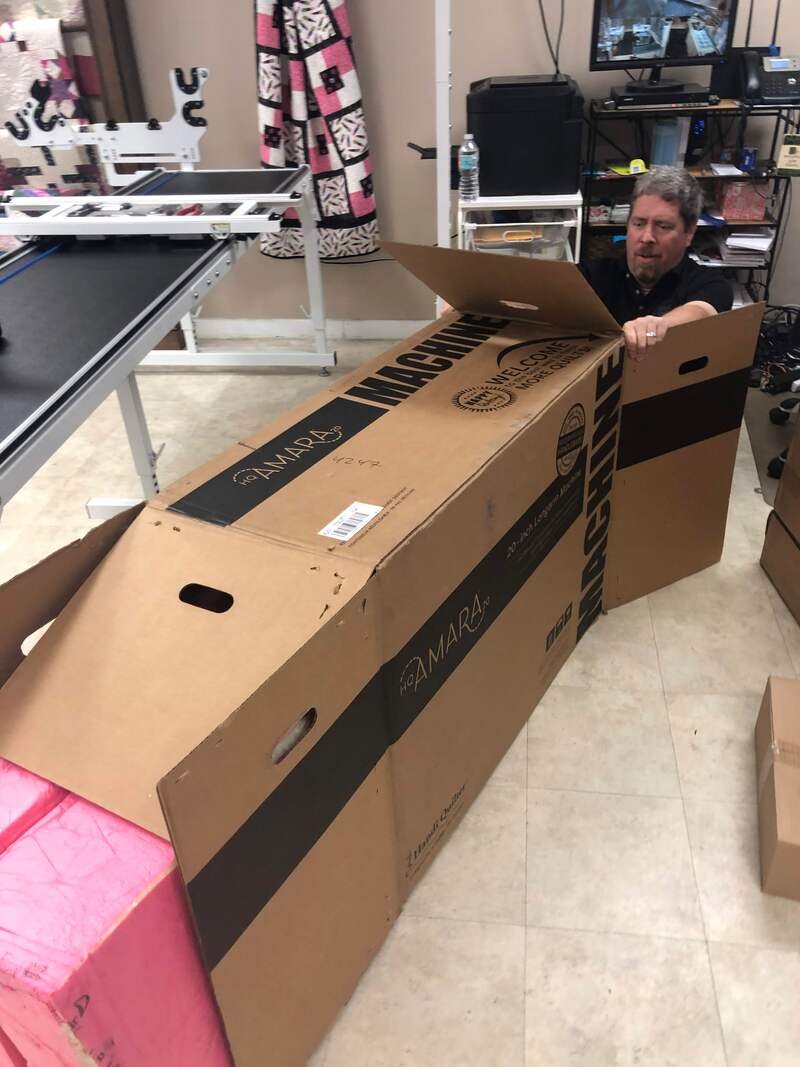
NOBODY TOLD US TO UNBOX EVERYTHING!
The BILT app starts by telling you to layout parts.  So we stopped to unbox everything.

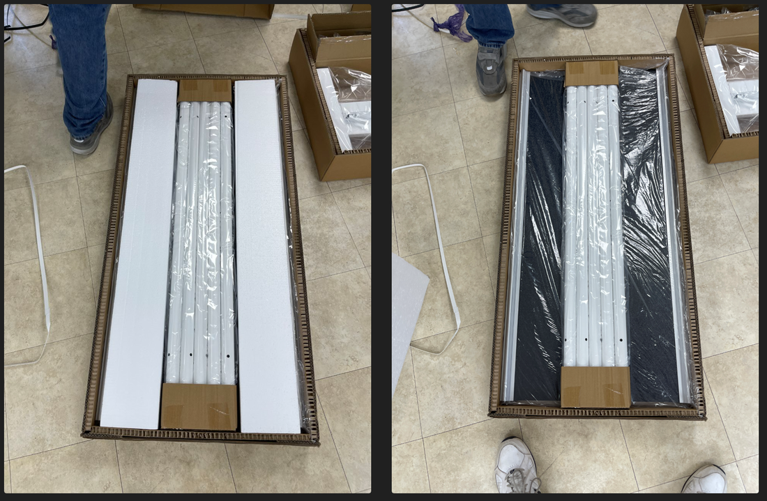
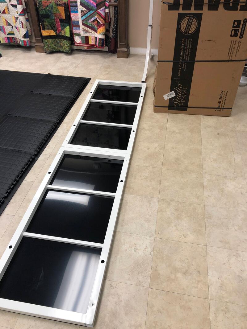
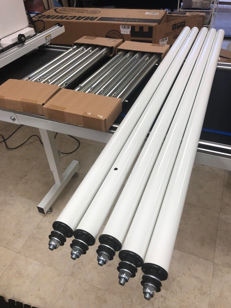
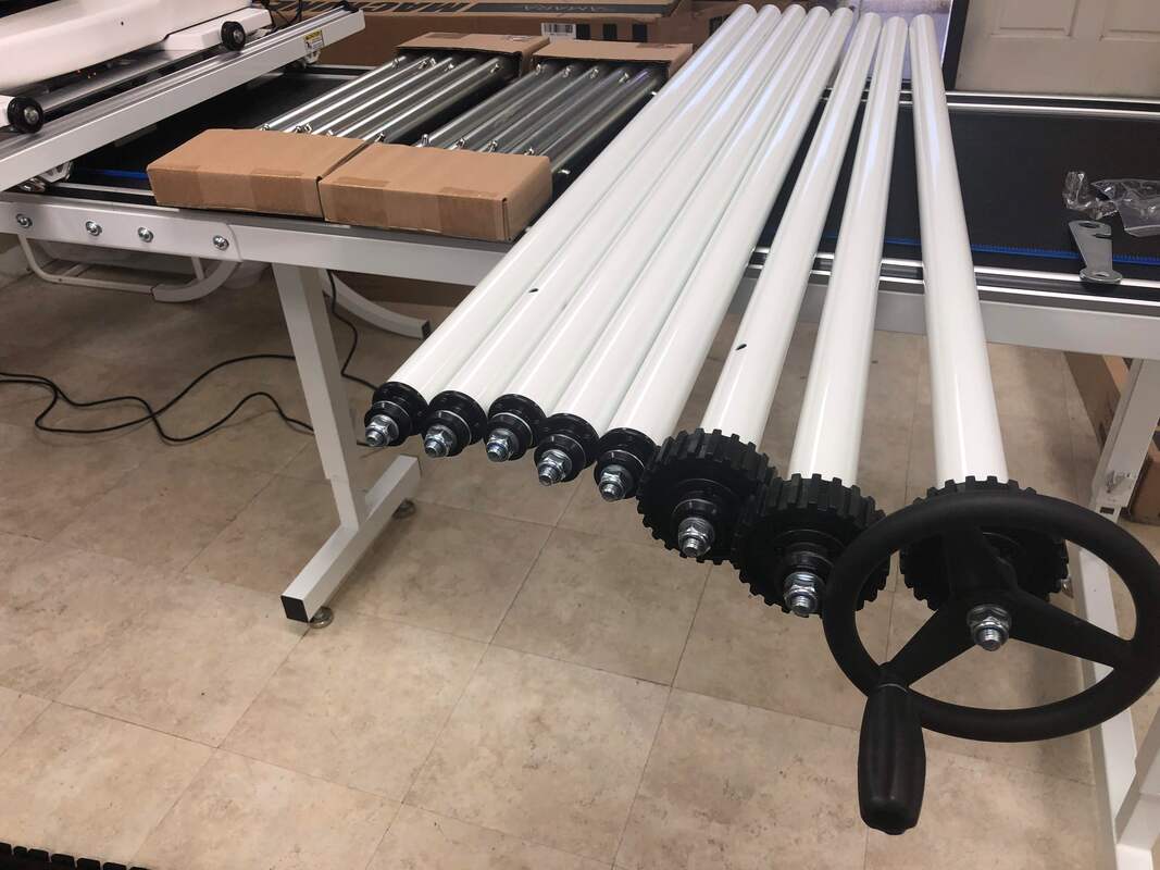
​BOX 2 - both of them - contain the 4ft table top and poles.

Remove the poles carefully so the cardboard stays on the ends and set them aside.  The table sections can be stood against a wall until you need them.
Picture
Picture
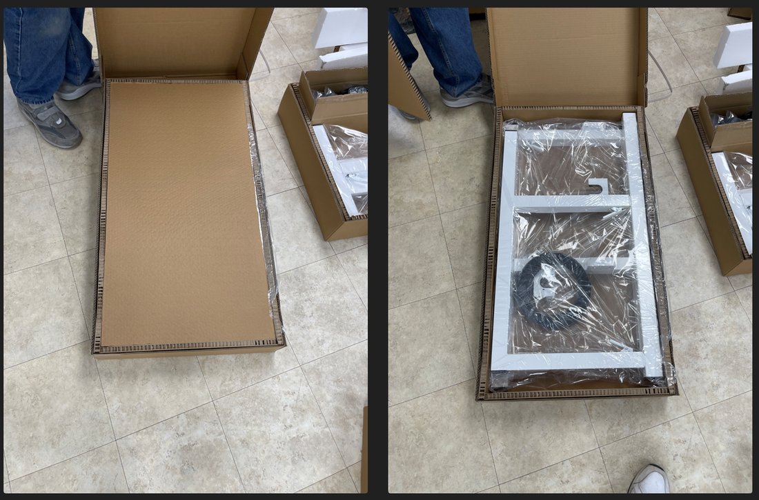
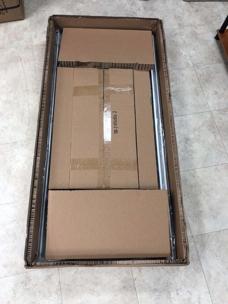
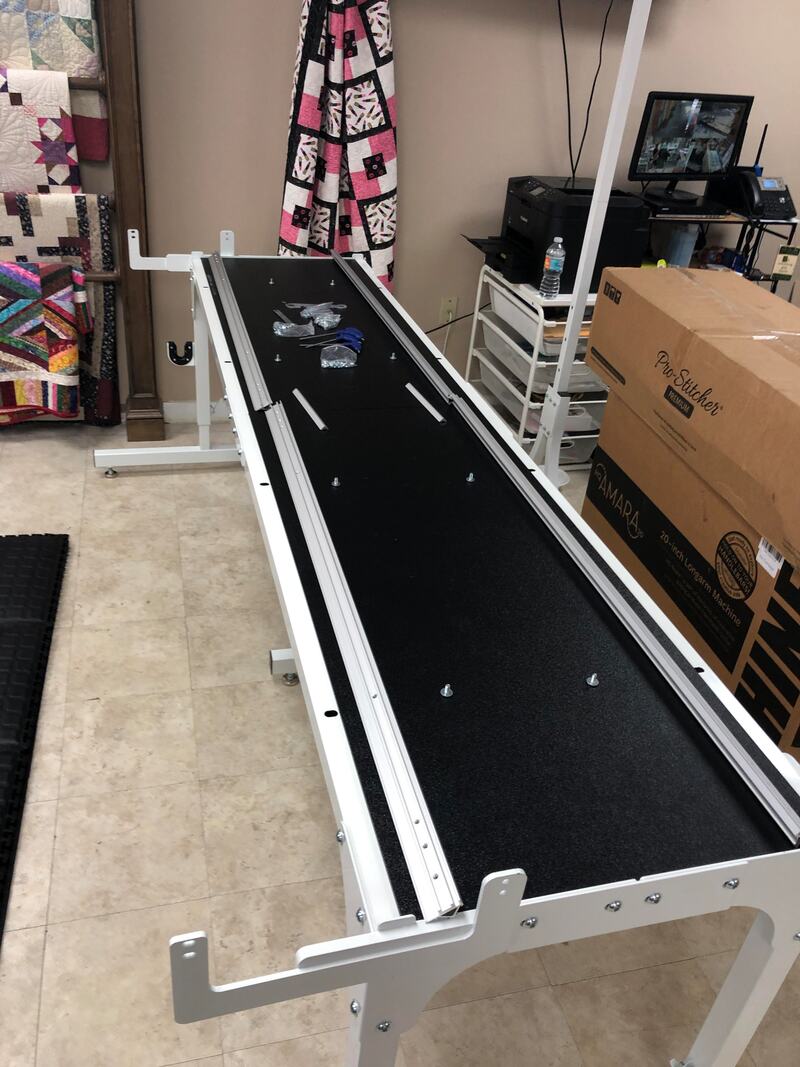
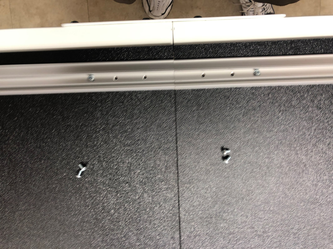
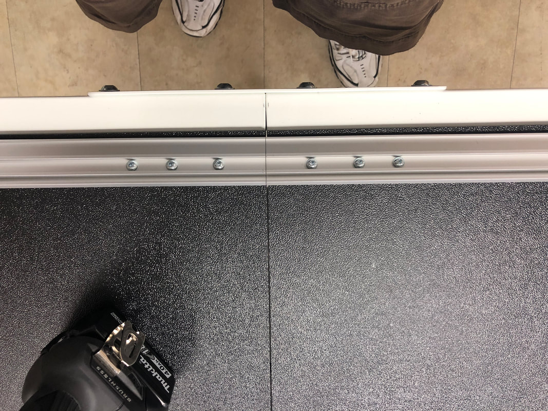
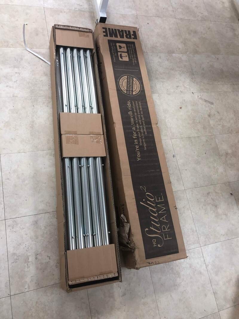
BOX 3: Contains the side legs and black track.

​Unwrap the legs and set the black tracks aside.
Picture
Picture
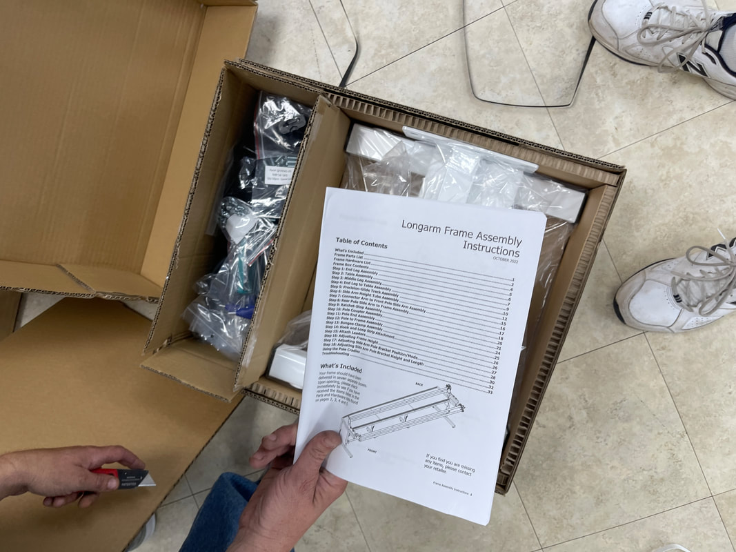
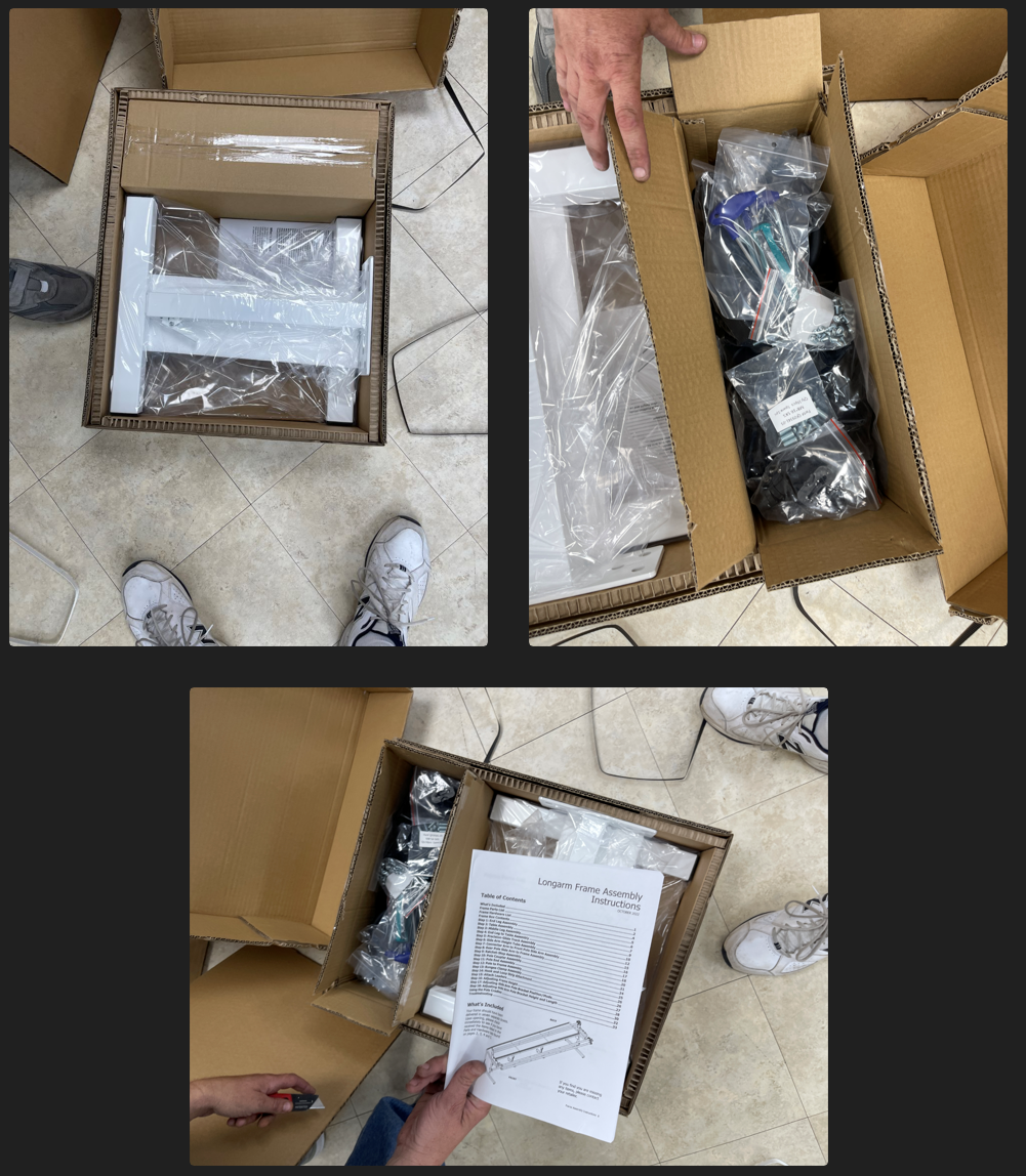
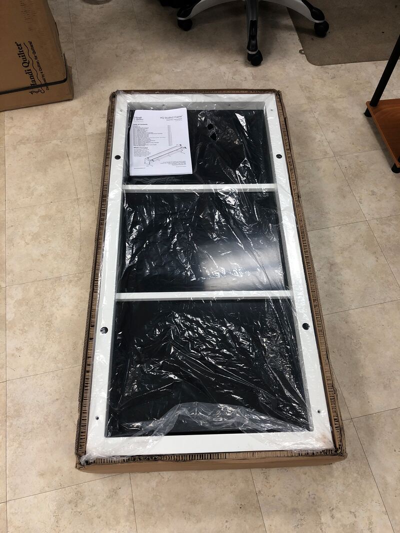
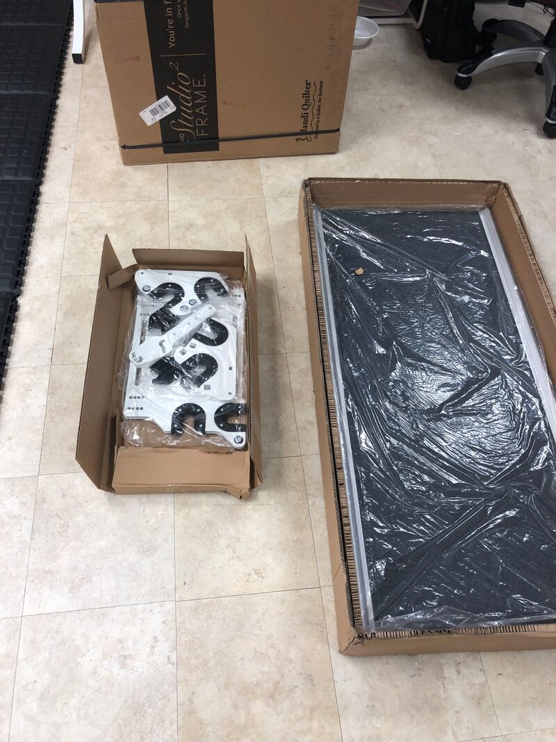
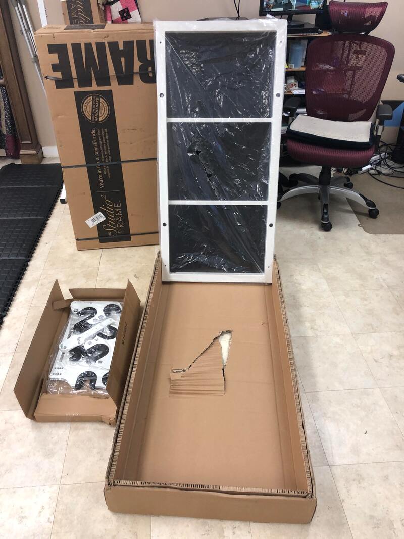
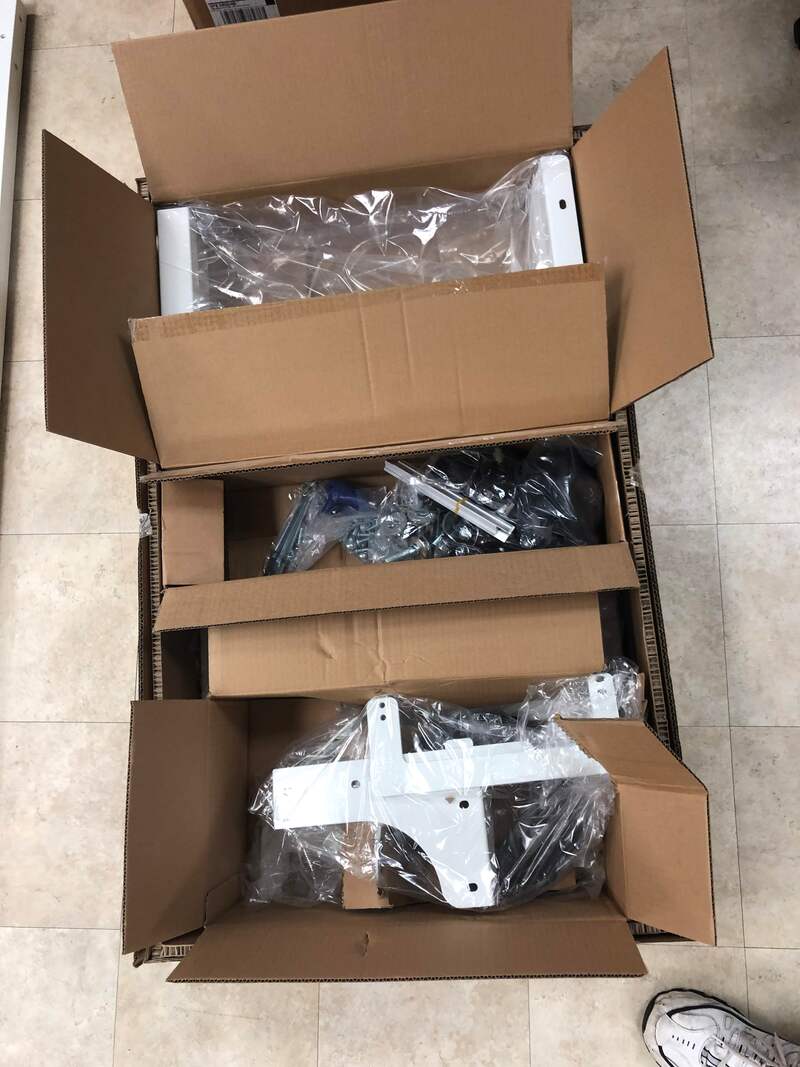
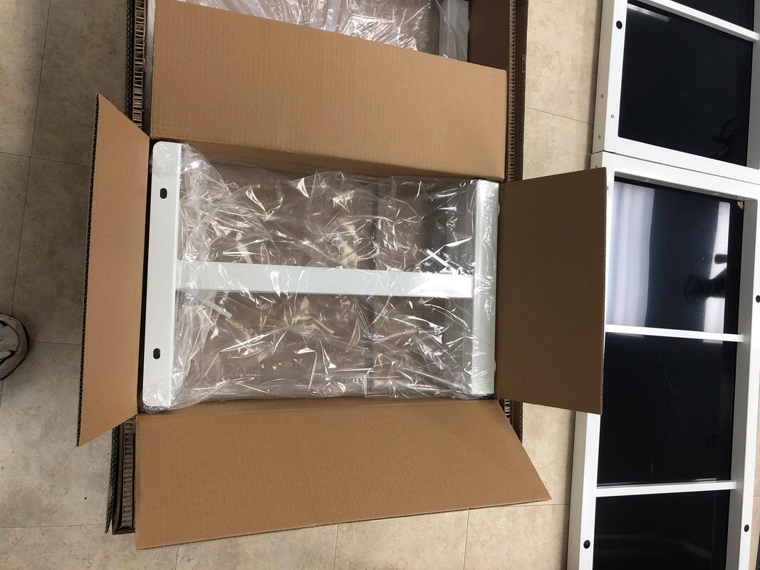
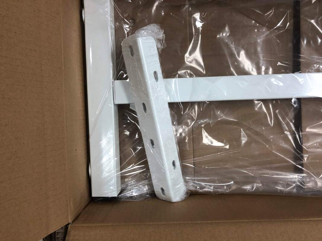
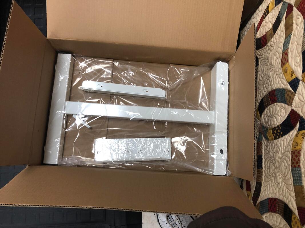
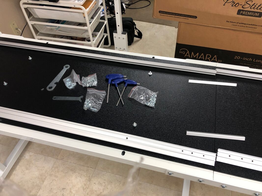
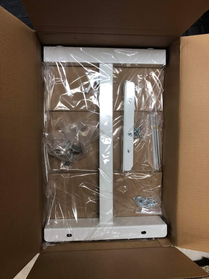
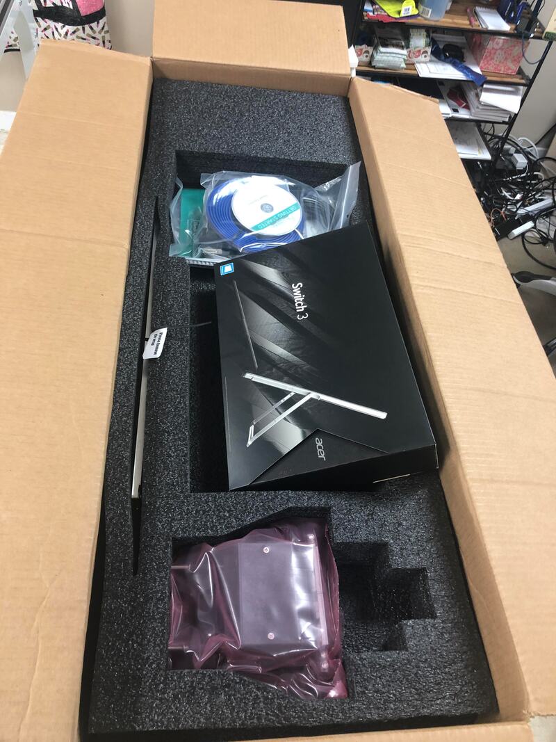
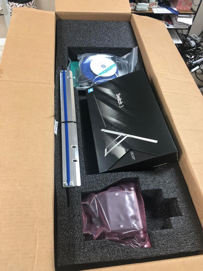
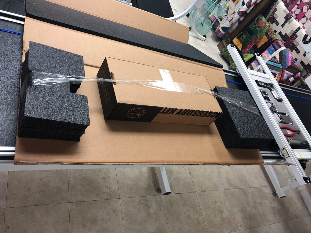
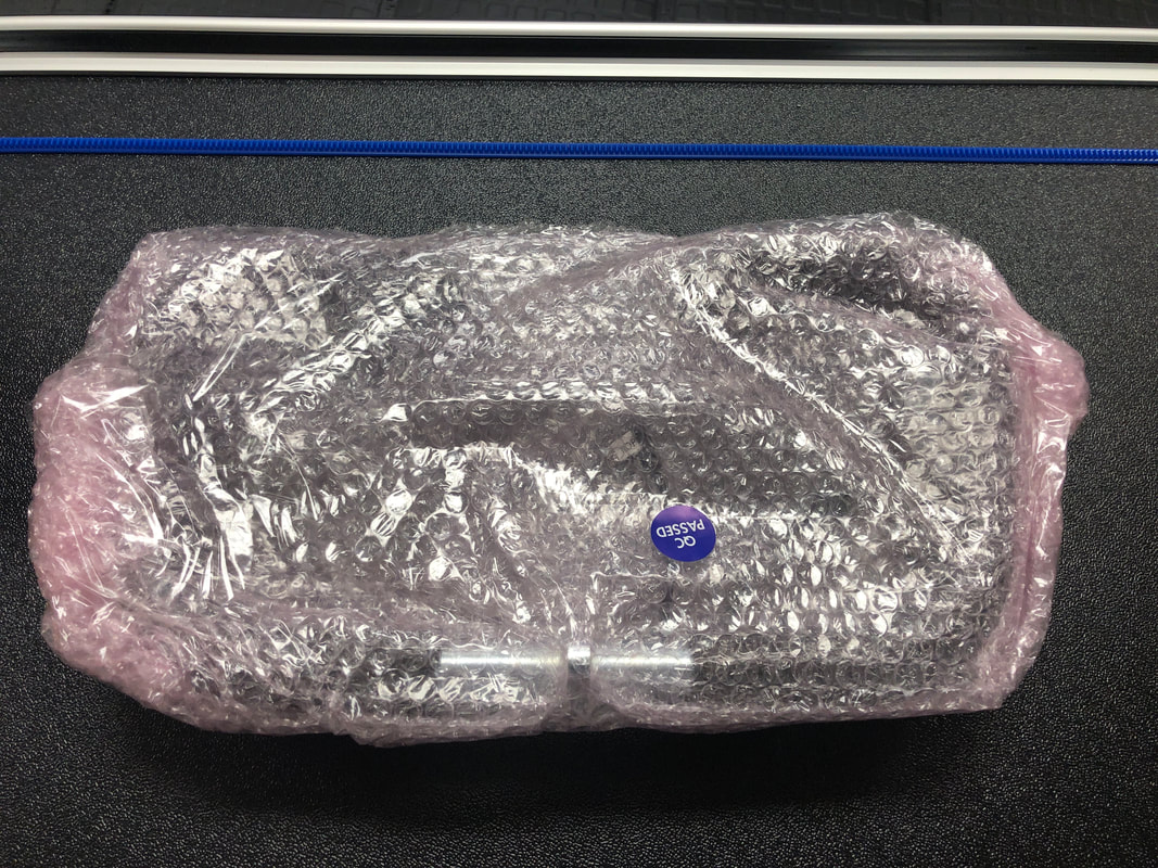
Box 4: Middle legs, instructions, and box of parts
Picture
Picture
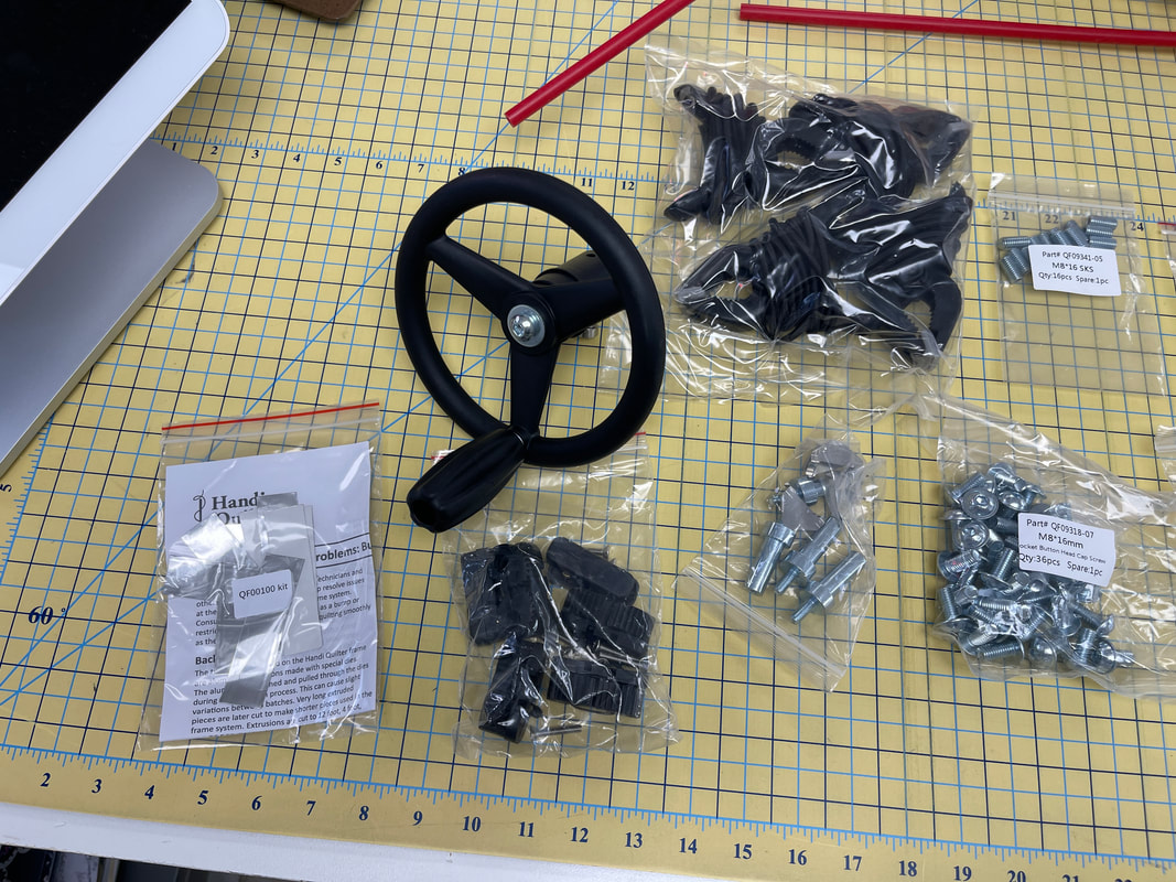
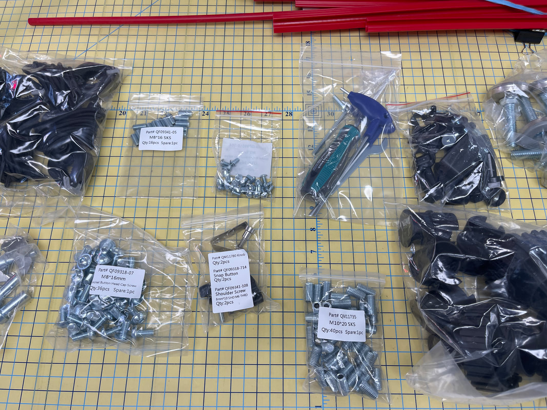
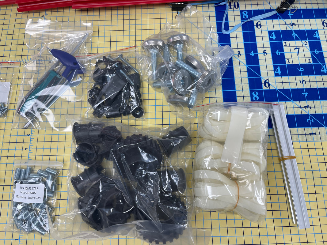
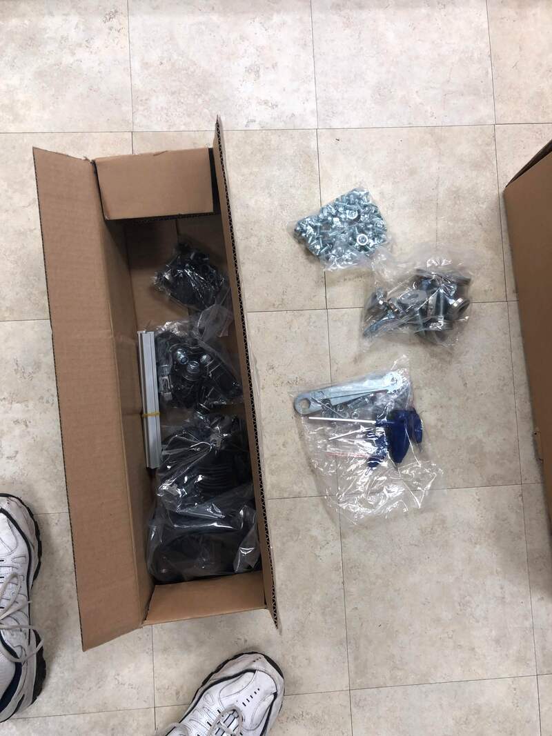
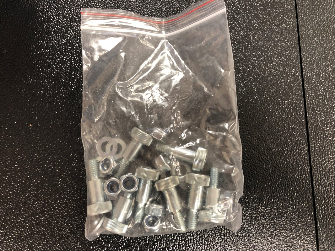
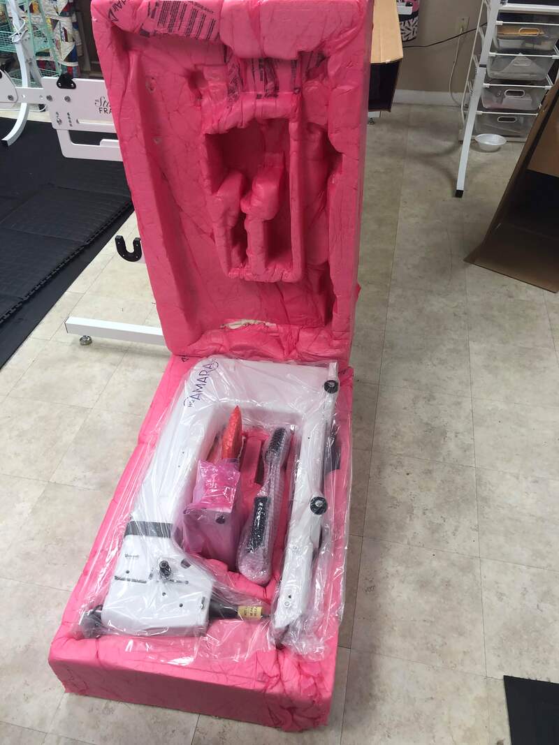
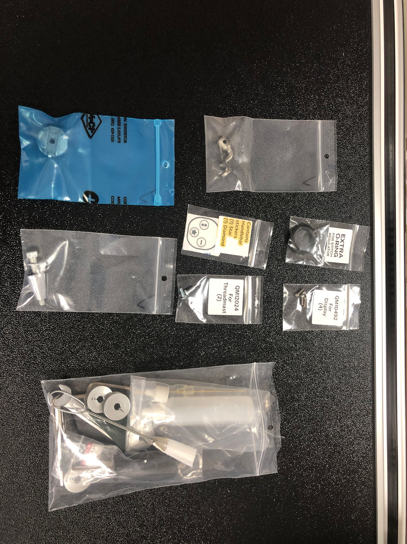
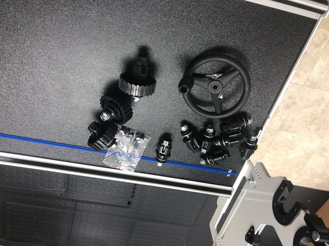
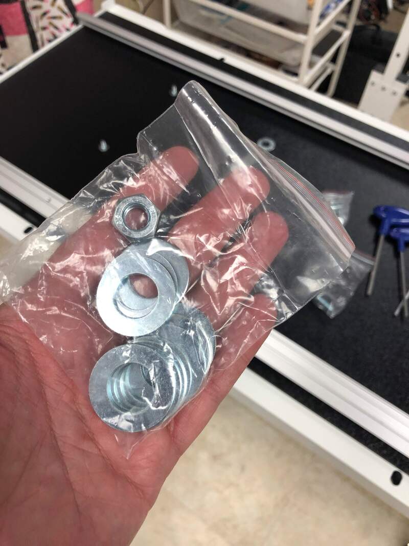
THE PARTS (from Box 4)
Picture
Picture
Picture
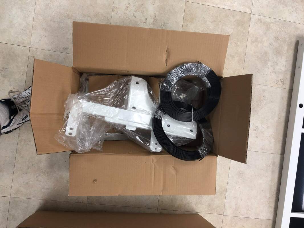
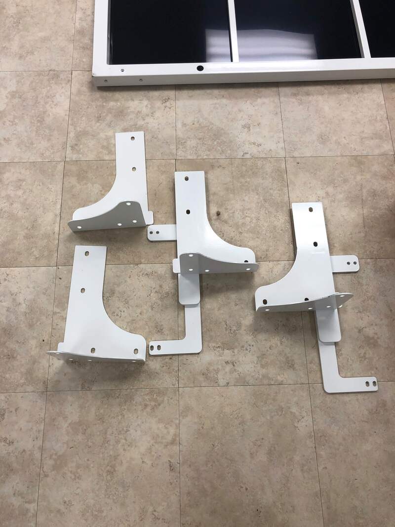
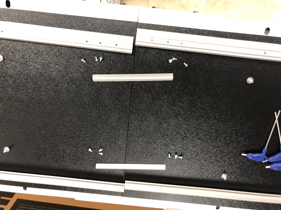
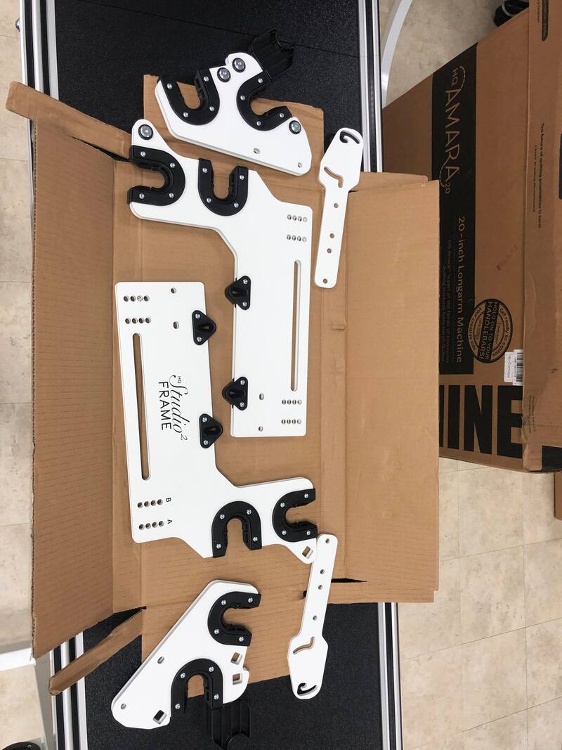
BOX 5: Side arms and related components

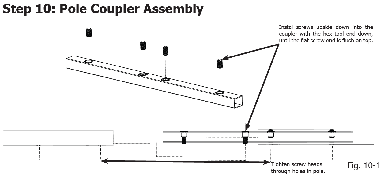
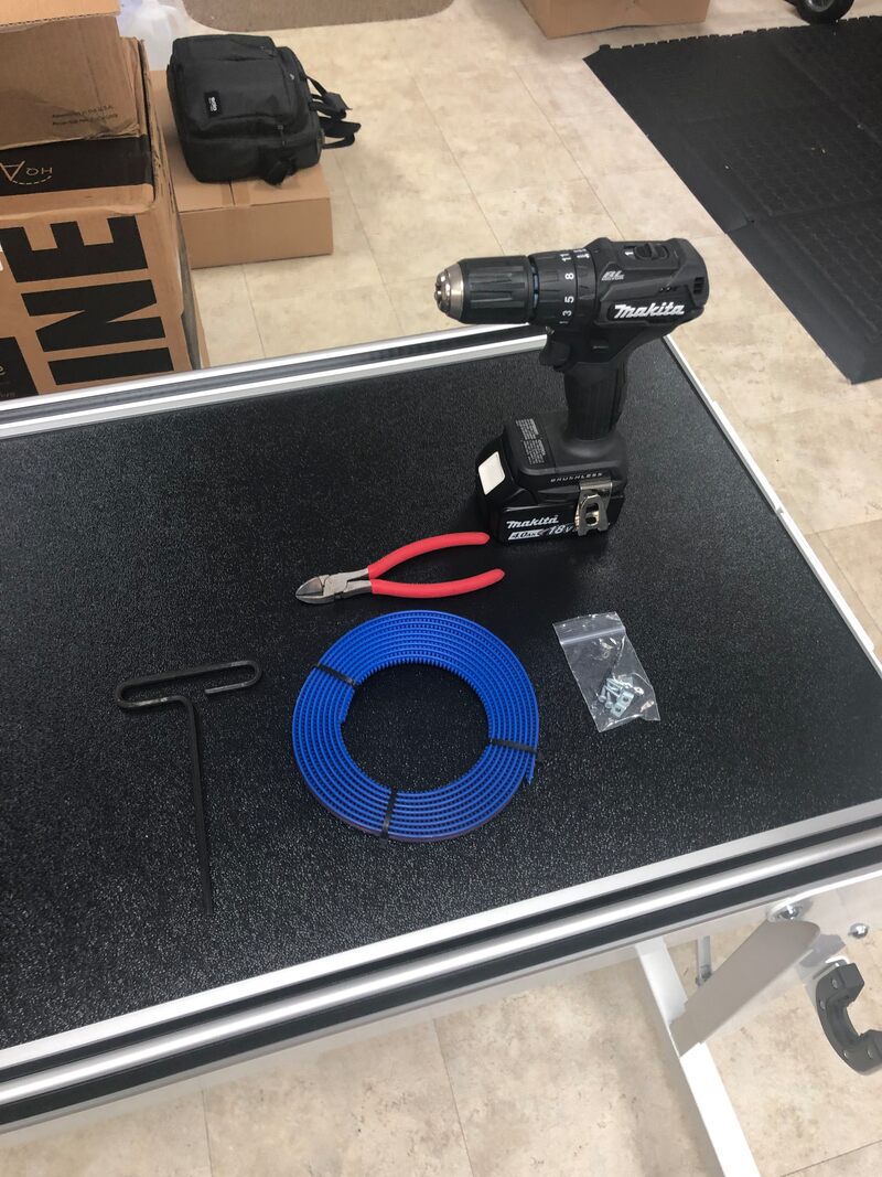
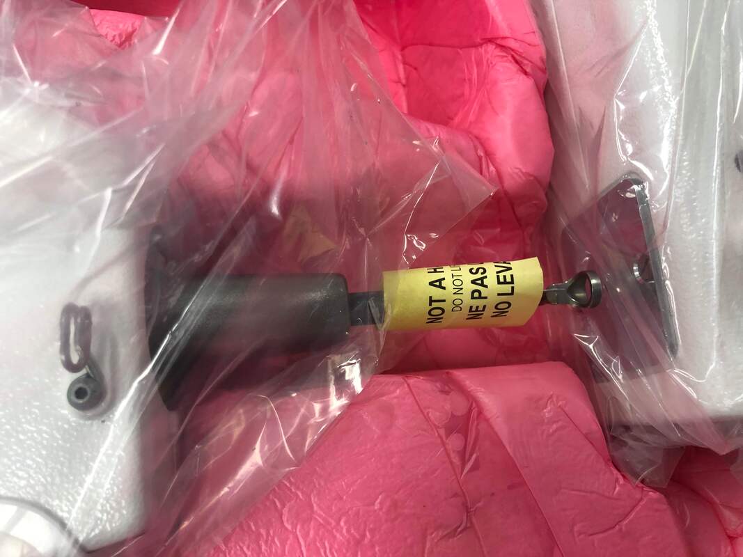
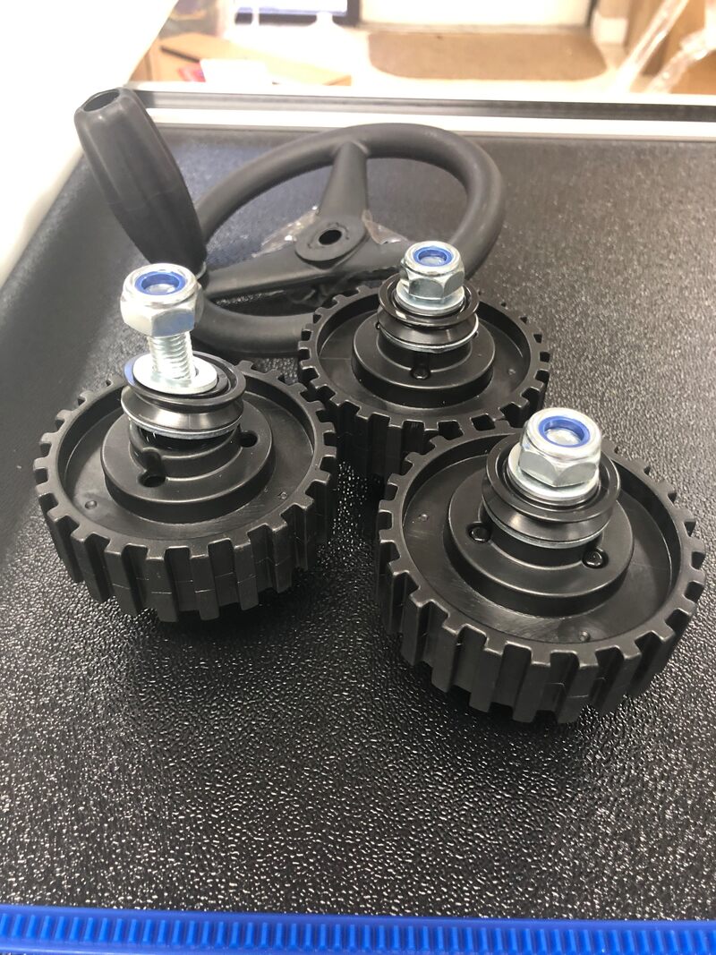
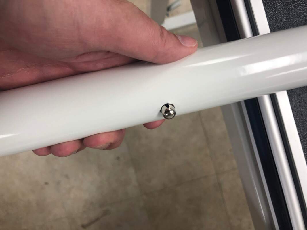
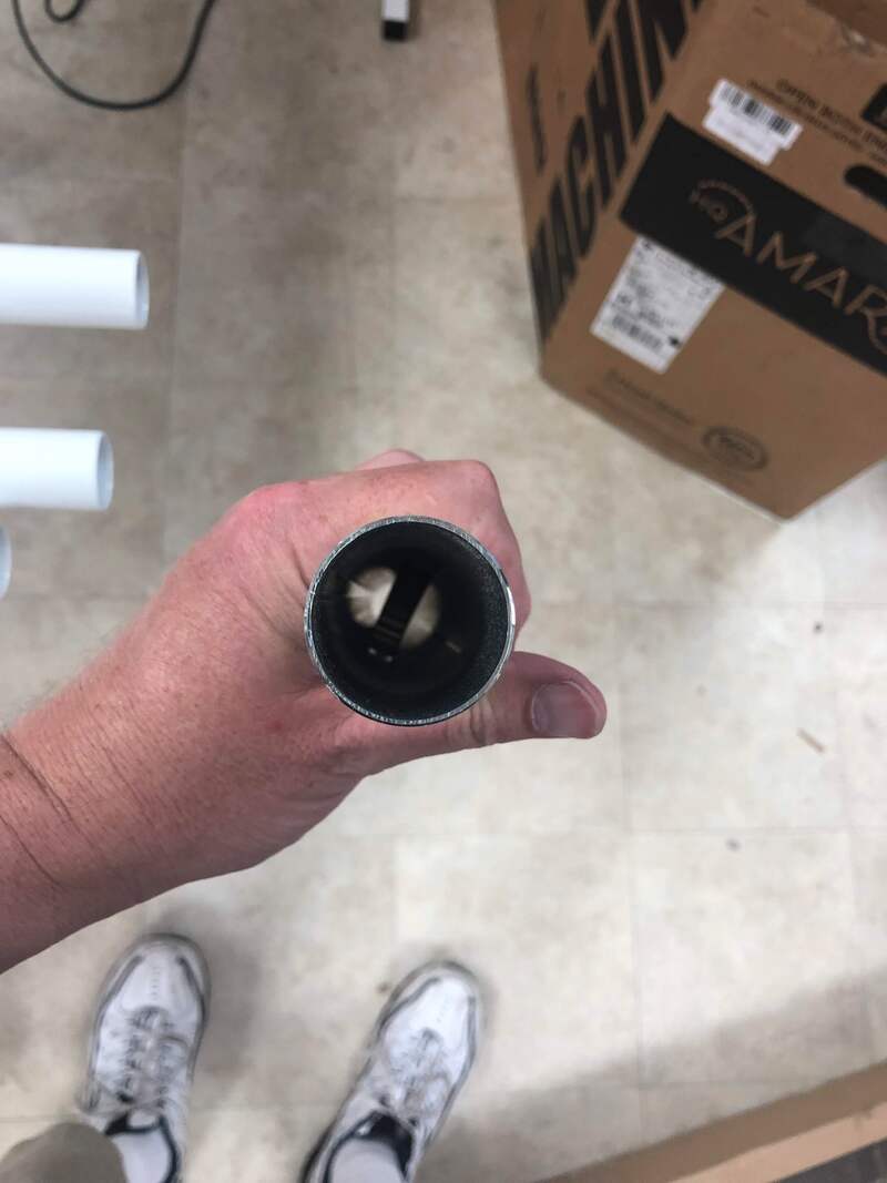
This efficiently packed box has a box in a box with a variety of parts...

Table Frame Coupler (qty 4)
Pole Coupler (qty 10)
Connector Arm - Left (qty 1)
Connector Arm - Right (qty 1)
Side Arm - Left (qty 1)
Side Arm - Right (qty 1)
Side Arm - Left Front (qty 1)
Side Arm - Right Front (qty 1)
Brace, Corner (qty 2)
Brace, Corner Mirrored (qty 2)
Tube, Side Arm Height (qty 4)

The 'pole couplers' are a new engineering marvel that will avoid sagging poles in the future.  Nicely done.  They are actually square bars with inset screws.
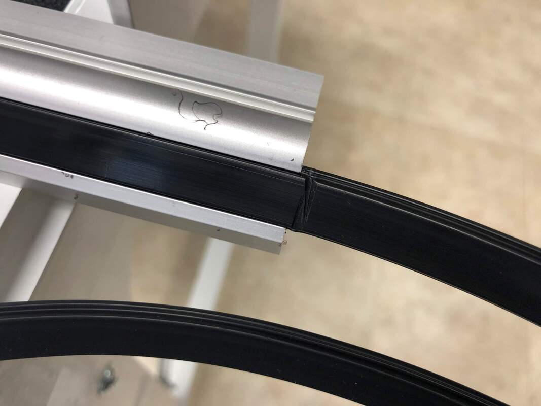
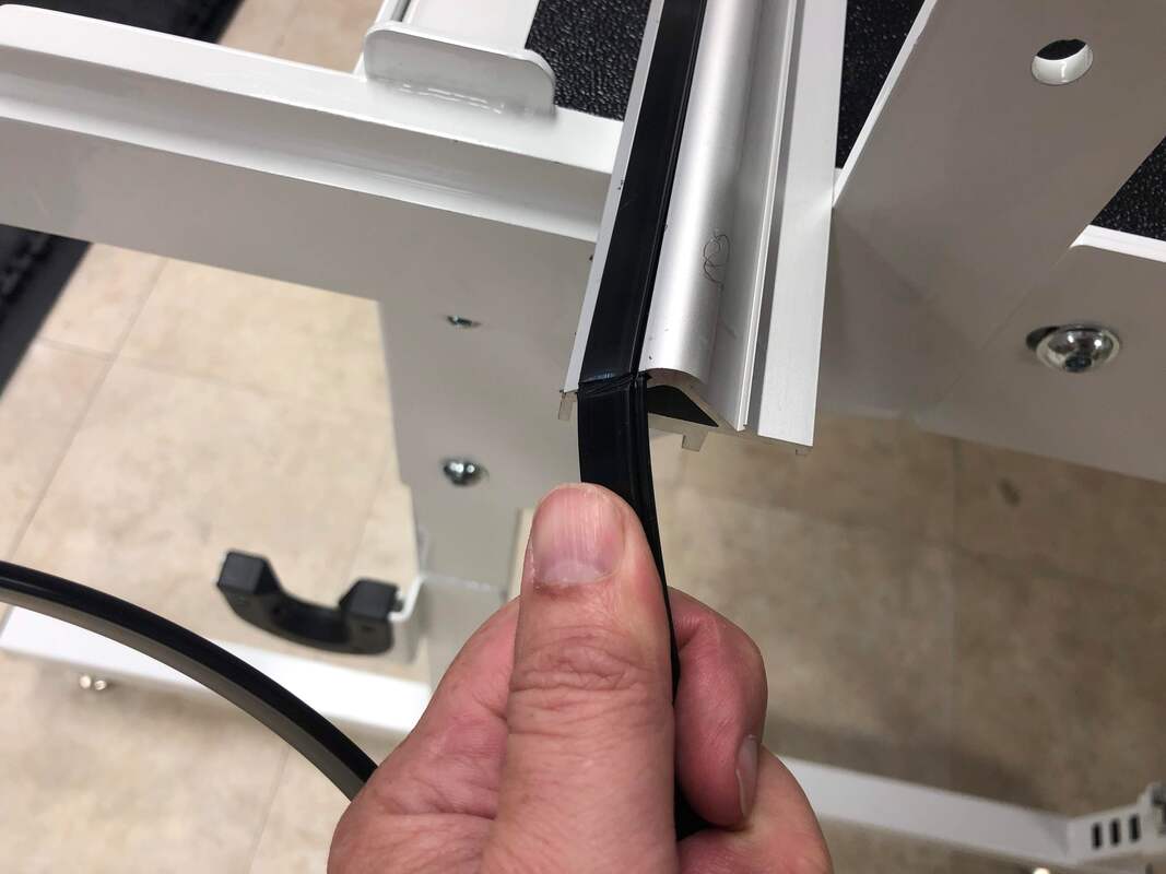
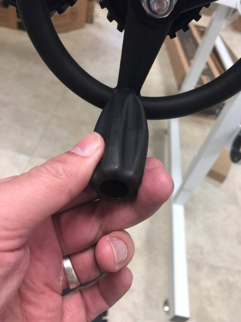
Picture
Picture

What confused us?

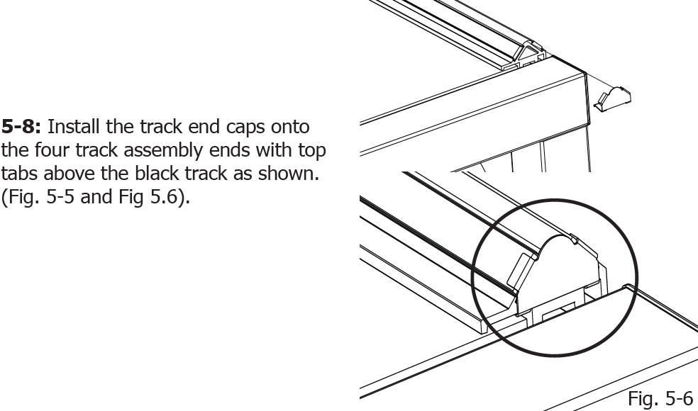
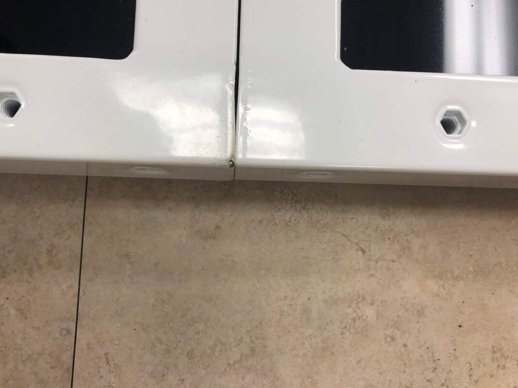
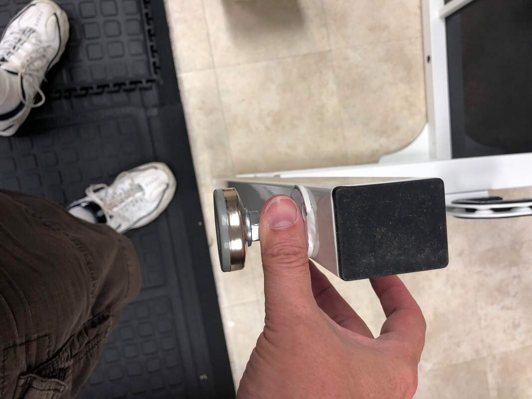
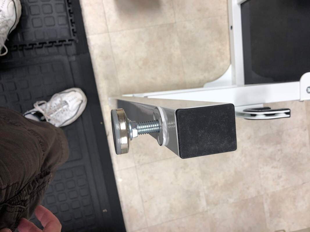
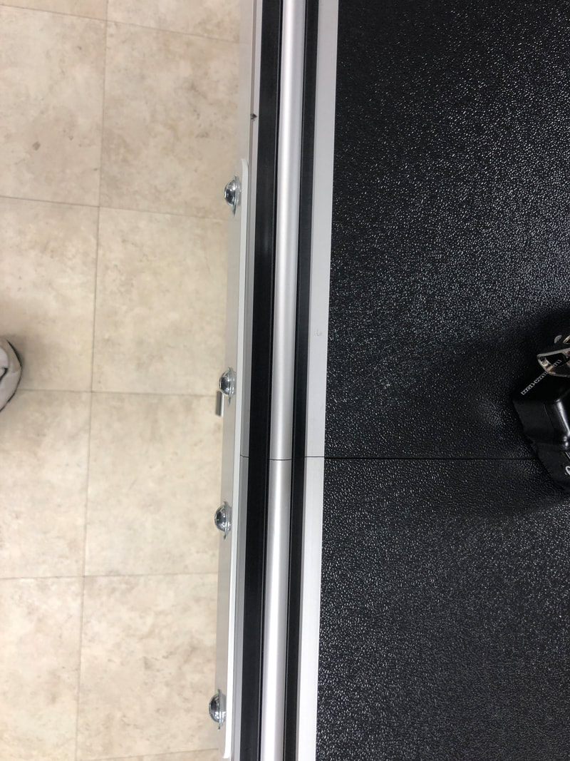
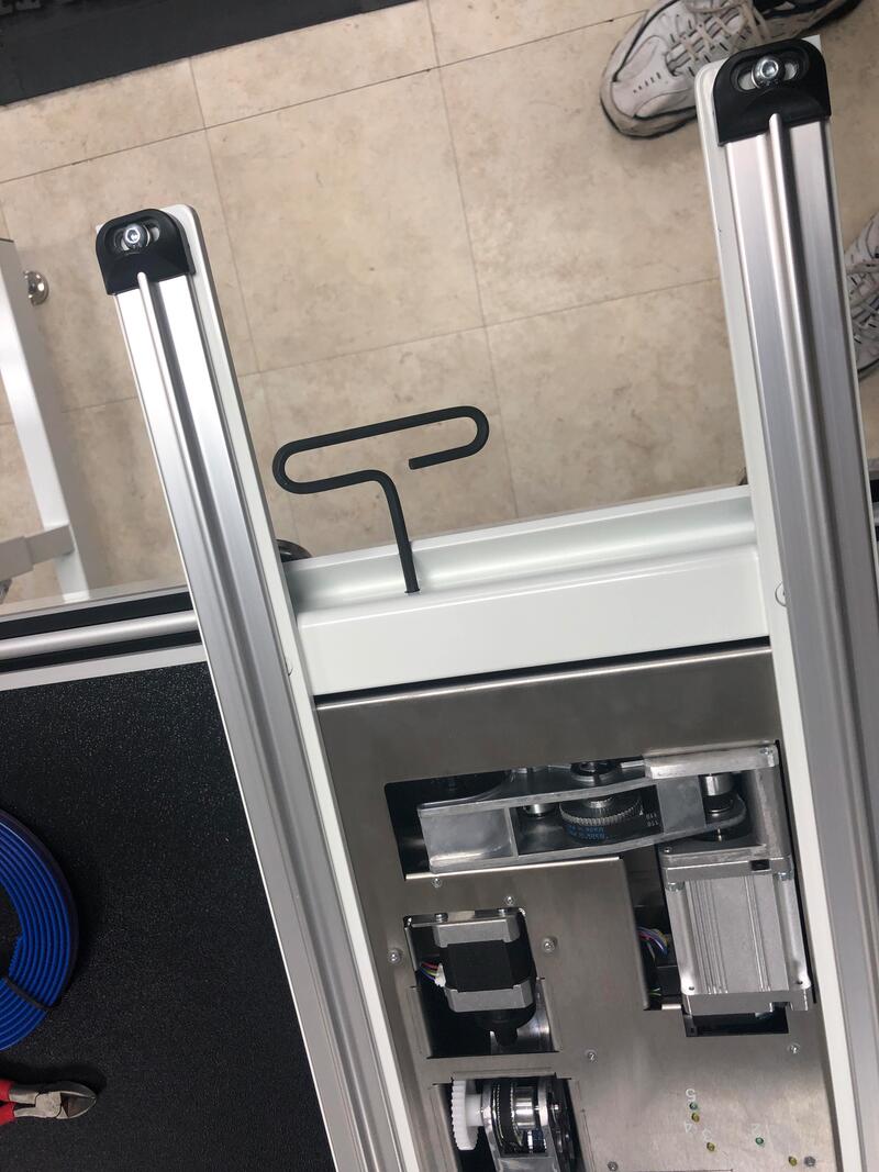
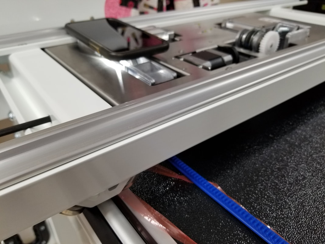
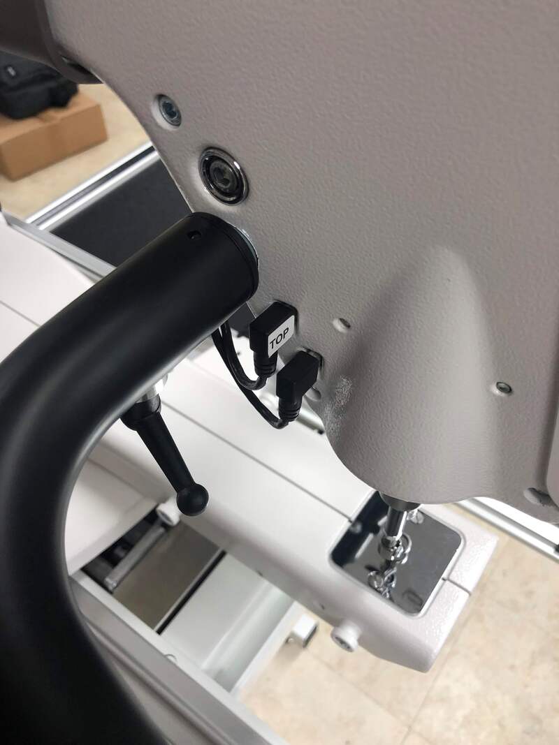
The BILT app shading made me think I was looking for black plastic clips.  However the track end clips a silver metal. The ends are more exposed on the new frame so this is a nice cosmetic touch.
Picture
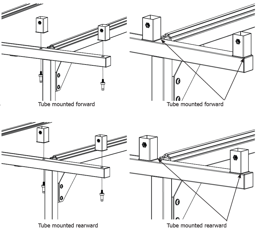
Step 6: Side Arm Height Tube Assembly
6-1: The 20” machine has the height tube
mounted rearward. The 16” and 18” machine
have the height tube mounted forward.

These parts basically move the rear poles back what looks to be half an inch when mounted to the rear.  We read that the screw hole should be to the rear and got it wrong the first time.  I don't think they could have done any better with the photos in the manual.  The BILT instructions used terminology that I was not understanding.


Picture
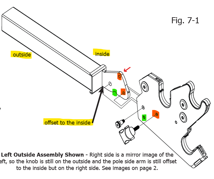
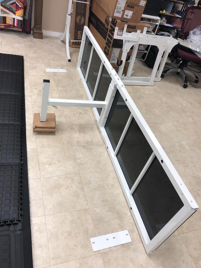
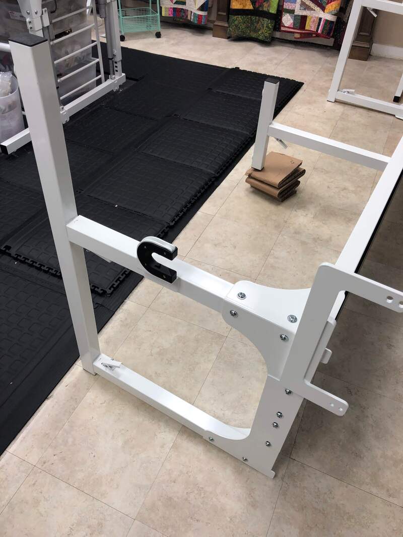
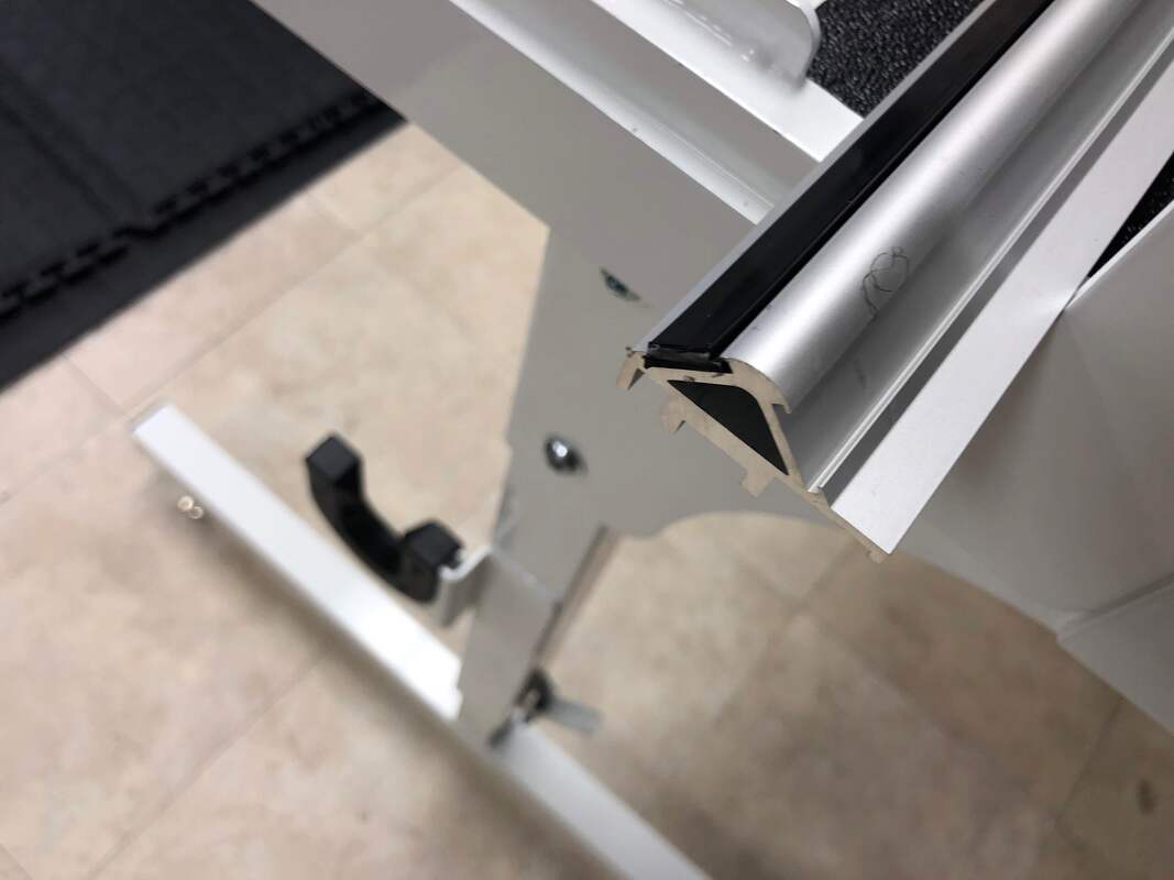
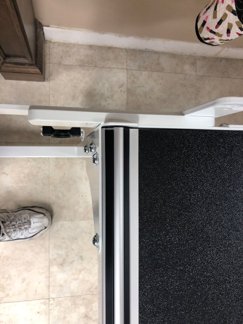
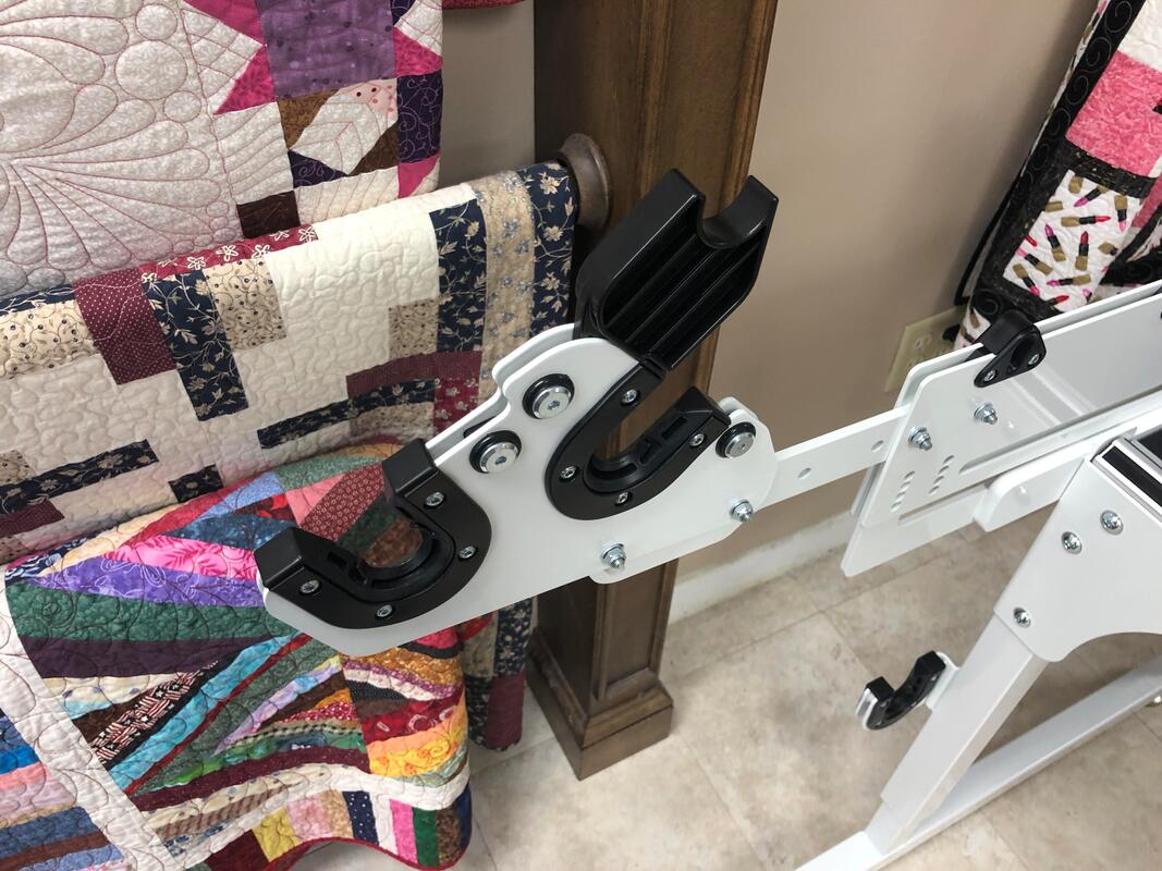
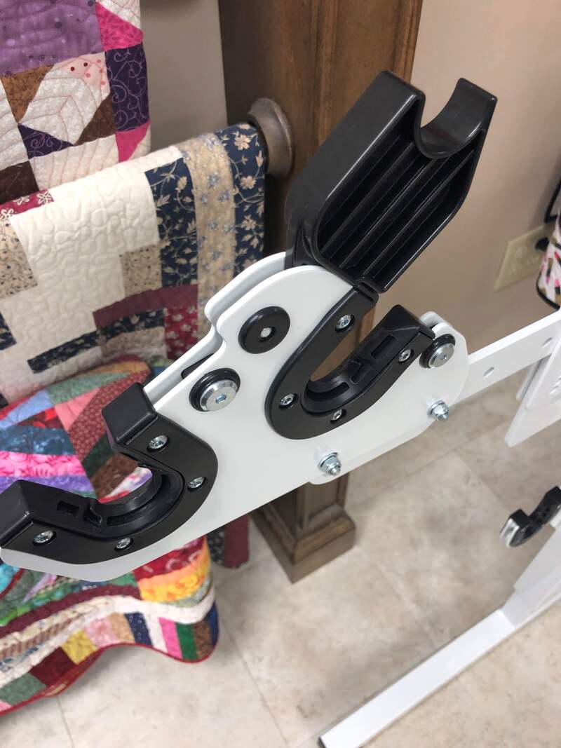
Step 7: Connector Arm to Front Pole Side Arm Assembly
The assembly of the side arms for the Studio3 is much easier to put together than on the Studio2 frame.  But here are a few things to look out for...

YELLOW:  Pay attention to the inside/outside.  If you put the bar on the wrong sides of the frame, the poles do not reach.
GREEN: The notch on the bottom aligns with a pin that is already inserted into assembly.  It acts like a pivot point when changing Clearview modes.
RED:  If you have ProStitcher, you will want to have the poles in the up position.  The new assembly is simpler and more stable.  You simply screw in the screw to whichever hole necessary.  In this case the TOP hole will give you a standard load.  Free motion only machines will likely use the lower Clearview mode.
​
Picture

What is really nice on the Studio3?

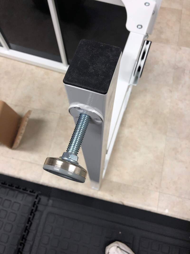
Extra Credit to the Engineers

This new pole couple assembly is rock solid and no more protruding button locks.
The pole ends go on without the heavy bolt and nuts.  However the jury is out on whether they have gone too cheap on the plastic ends.
Picture
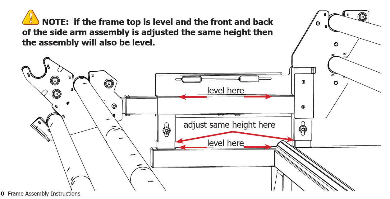
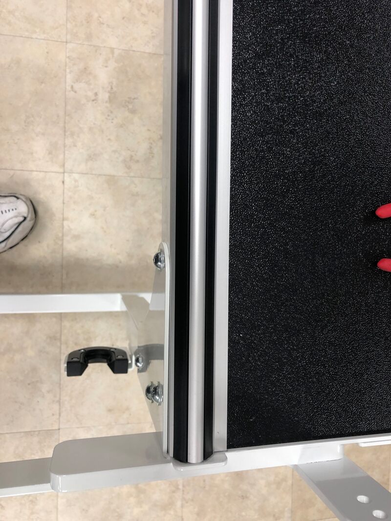
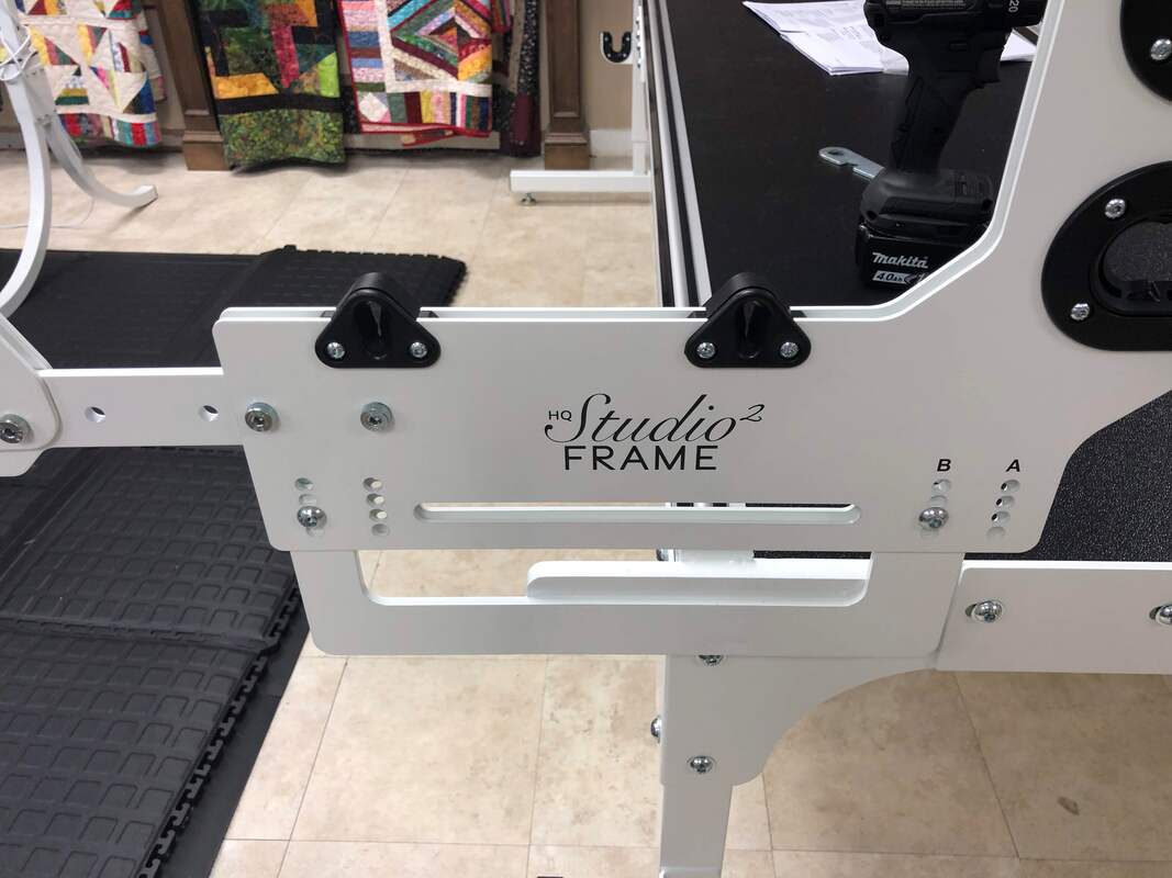
Step 18: Adjusting Side Arm Pole Bracket Height and Length
We found the height of the poles to be adequate at the lowest setting (resting) on the side of the frame.  This was with a PS carriage and an Amara.

The length of the front poles can be adjusted to your preference as long as the needle bar/hopping foot does not hit the front bar before the machine reaches the end of the carriage.

Yes - you actually get a half inch of extra usable space compared to the Studio2.  The back throat of the machine used to hit just slightly before the wheels would reach the end of the carriage.  This is no longer the case.  It may be a little less than half an inch, but the ladies were pleased.  (You still will have the quilt rolling up and taking away throat space as you go, so plan for it.)

Picture
Picture

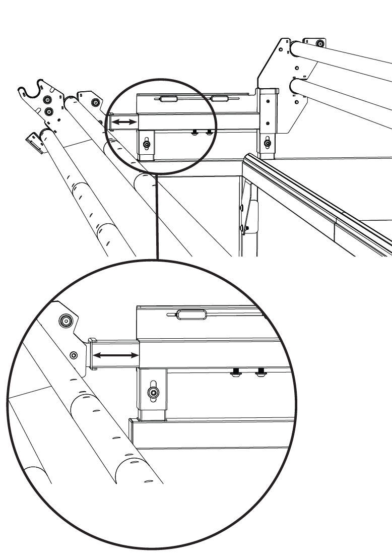
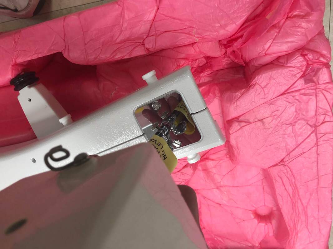
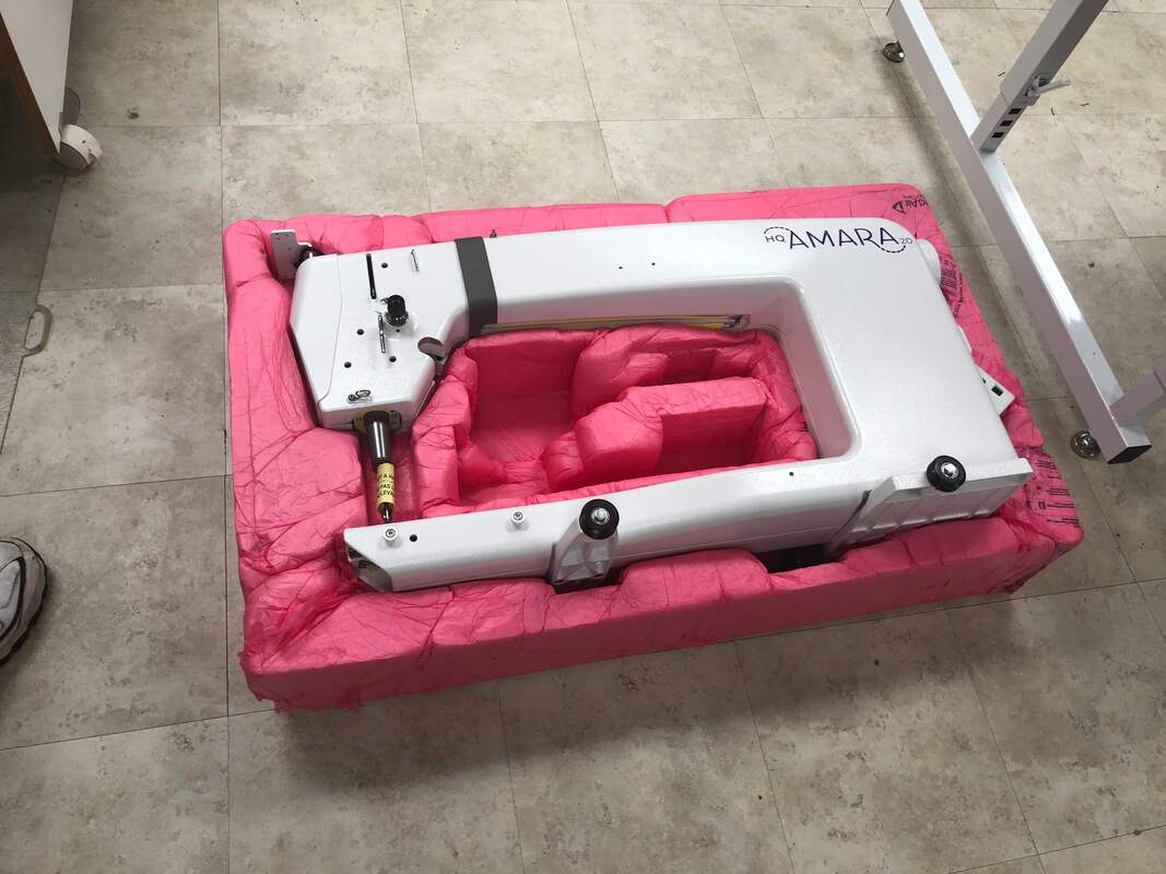
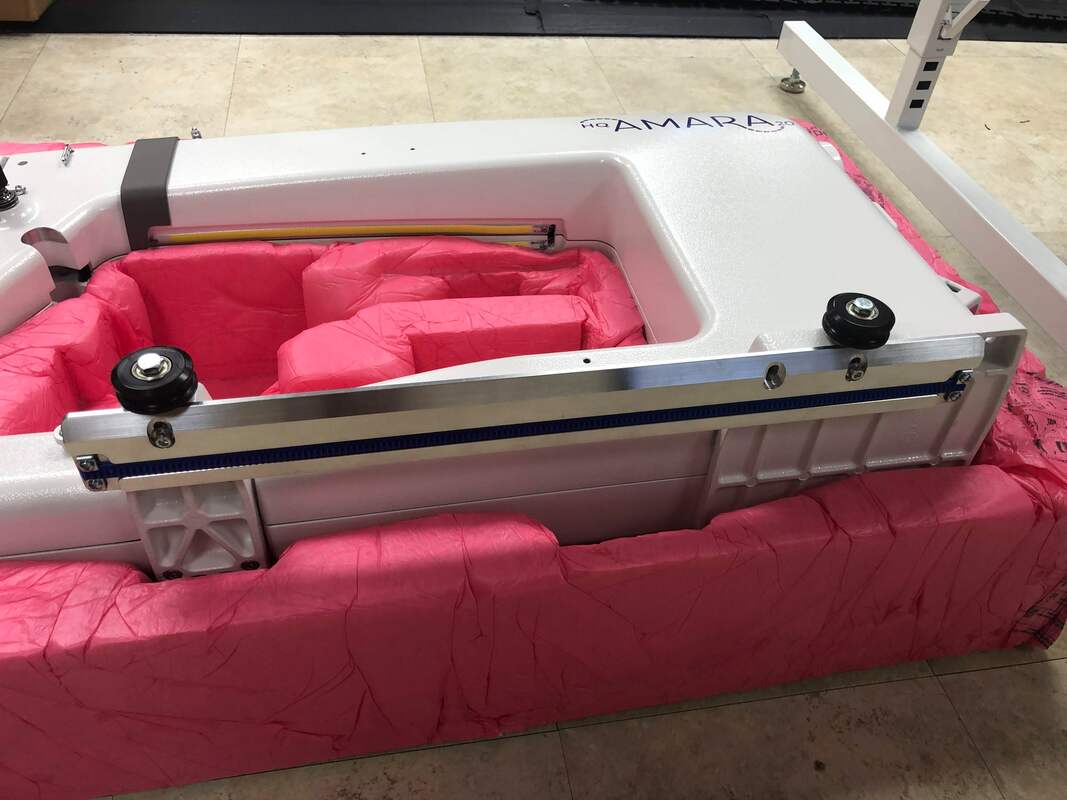
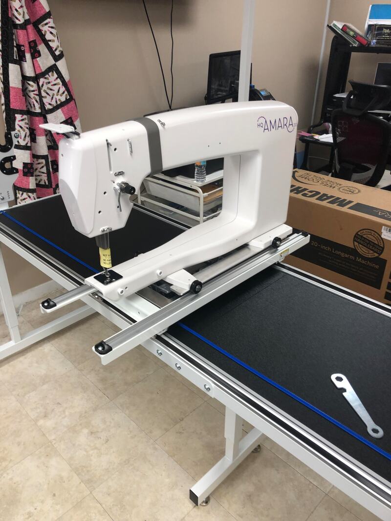
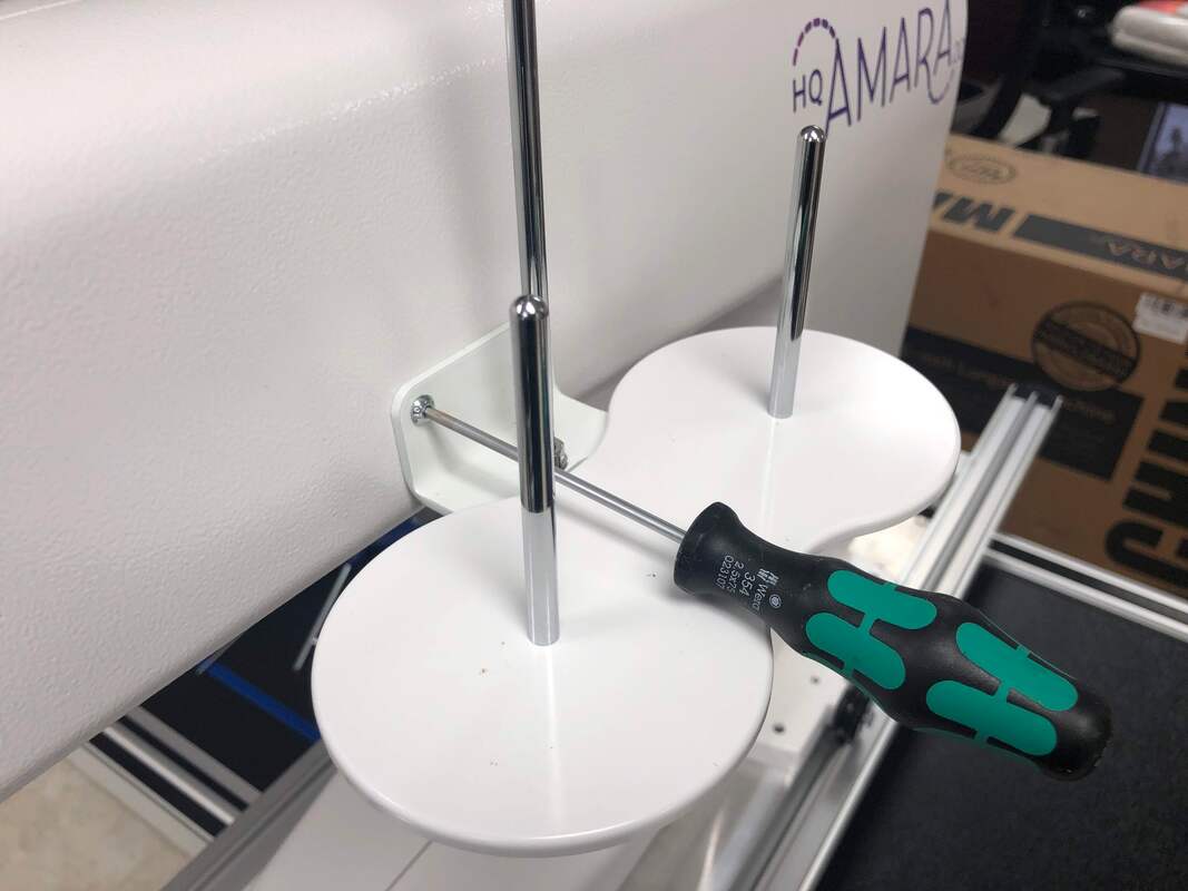
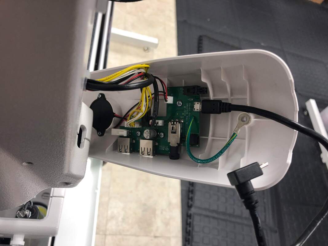
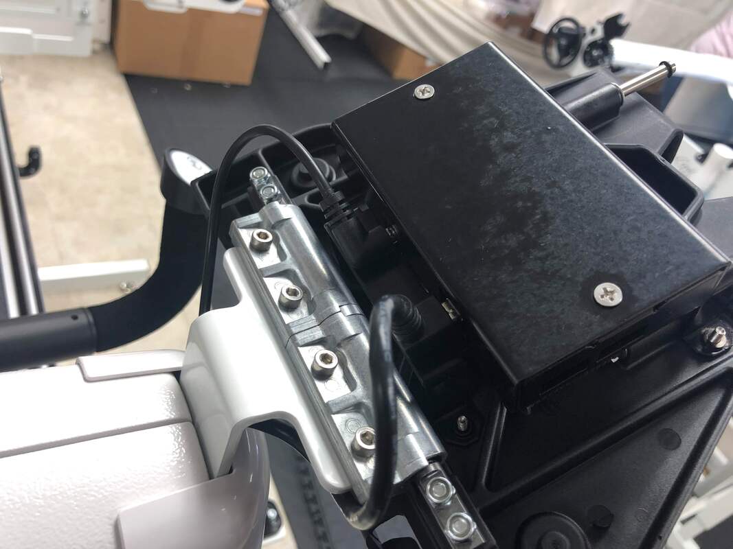
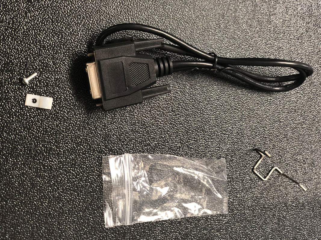
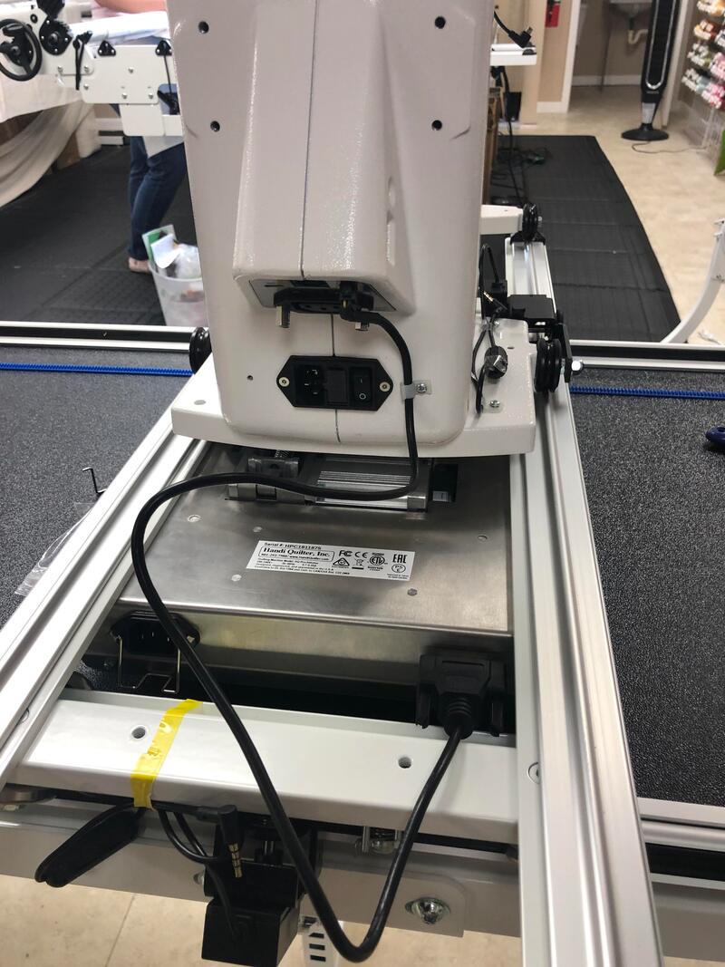
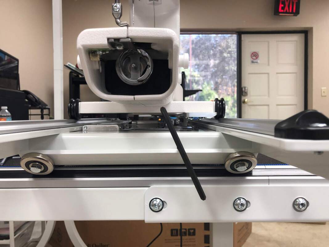
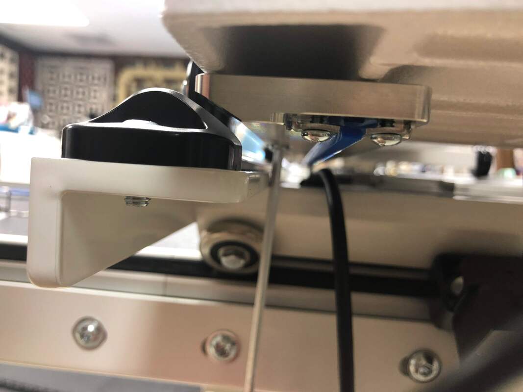
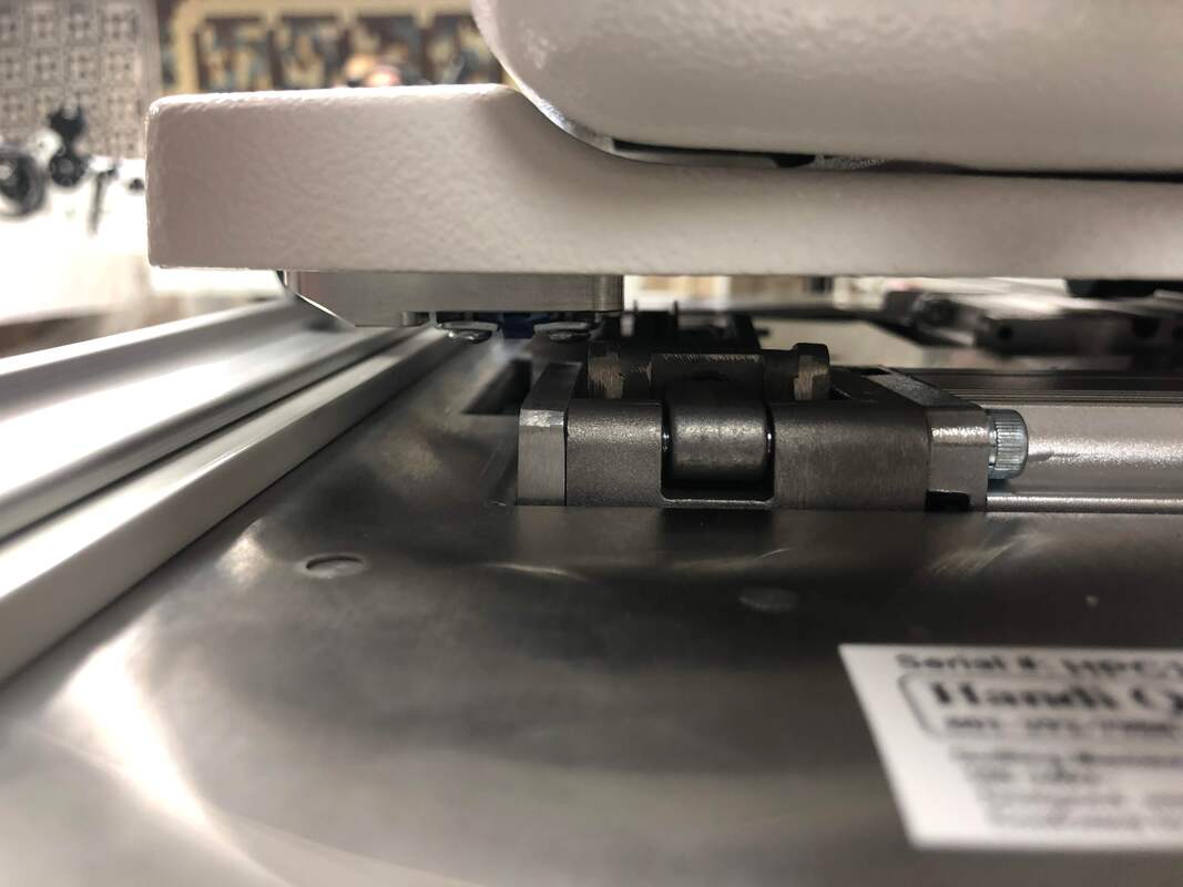
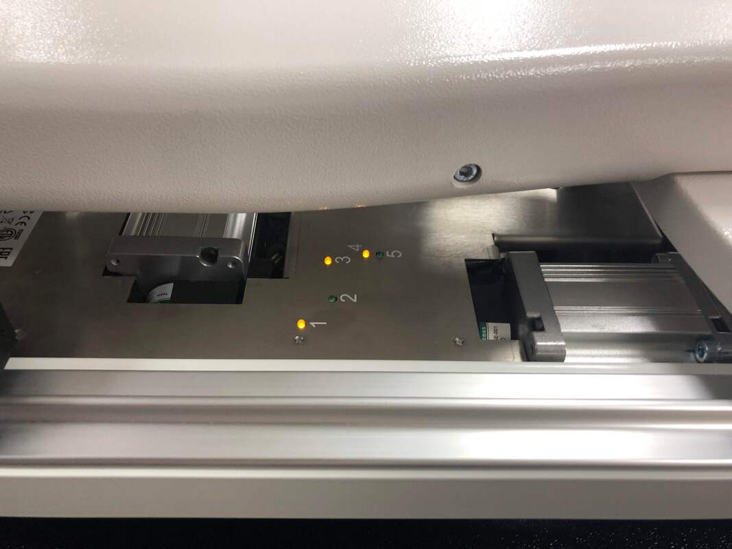
Picture book of a common installation

Float your mouse over the pictures to read words of wisdom.  Click on a picture to enlarge them.  
The MKQ Installation Guide supplements the instruction manual and shares tips we have found helpful.  This material does not directly pertain to installing a Loft or LittleFoot frame.
mk_quilts_installation_guide_for_owners_july_2022.pdf
File Size: 378 kb
File Type: pdf
Download File

hq-studio-2-frame-manual-03-22-22.pdf
File Size: 6689 kb
File Type: pdf
Download File

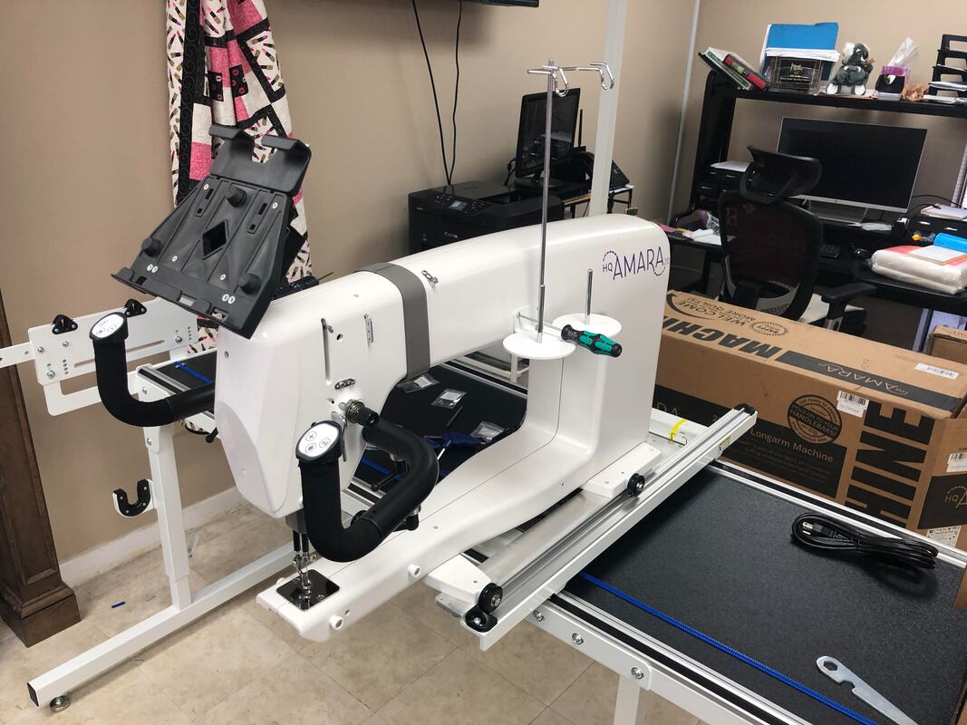
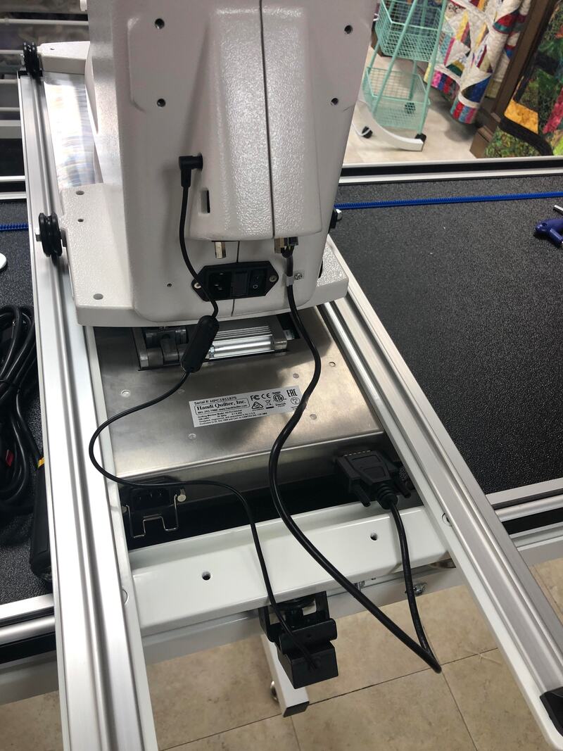
Note:  This Studio2 frame is being set up at only 8ft.  This leaves out the middle section of parts.  The middle section is either 2ft or 4ft in size, making the 10ft or 12ft frame dimensions.  The Amara and Forte are essentially the same machines, but the Forte and Infinity go on the larger Gallery2 frame.  All the Gallery parts look similar to the Studio parts.
Box 1 has the two main table segments.
Take photos of possible damage. HQ will replace items damaged in shipping.
Installation Instructions
This install may shuffle a few steps listed in the instructions.
Remove and open extra boxes.
Set sidearm parts aside. REMOVE the rails from the table segments.
Damage was only to the underside of the table.
Layout table to validate space. (8ft setup simply removes the 2ft segment and one leg.)
Third section is 2' or 4' depending on size ordered. (not used with 8' config)
Use the large bag of 65 screws to assemble table base. There will be one left.
Set black track aside.
Table corner pieces.
Leg pieces.
Brackets for the joints are wrapped in plastic wrap.
Take note of table corners. Small damage can lead to misalignment.
Small cosmetic damage is going to be covered by other parts and won't effect the frame.
Side legs can be assembled. The batting bar hooks go on the outside.
Careful to keep the leg extensions at the minimum height.
At 8', the extra leg and parts can be saved.
TIP: Put something under the leg to hold table in a perpendicular position.
Side plates will be used when the side legs are attached.
Attaching the side legs requires a top down approach. Do not tighten the screws fully.
The screws on the bottom/back of the table are installed AFTER the frame is stood upright.
Casters or rubber feet should be installed. You may need a tool to push past paint in the threads.
I use my thumb as a guide to make sure all feet are at the same height.
Stand up the table - Use help when available.
Start tightening screws at the table joints, making sure the parts are aligned and smooth.
Go around and tighten all 64 screws, insuring that the legs are straight according to the instructions. Don't forget the center leg(s).
Layout metal rail parts on the table.
The screws and metal inserts are critical to align the rail segments.
The third screw hole in is a stopper. Insert screws completely, then insert the metal piece.
Align the two tracks and secure the other four screws.
Inspect the rails to assure a smooth connection.
Tight and smooth, or redo.
Unwrap the black tracks. Check for damage to the surface of the tracks.
Block the rail so one end hangs off the table.
Insert the black track into the rail. The straighter you extend the black track, the less shavings will occur.
Depending on the table size, you may need to cut the excess off.
Crimp the black track from both sides to create a notch.
Notch.
Bend to snap.
Repeat track for both sides. Flat side of rail goes toward the inside of the table.
Align the front track with the front end of the table and tighten it down. Note, this is different than what the instructions state. Trust us.
Repeat on the back rail but leave the screws loose. Float the back rail.
Saving extra parts from 8' build. Table can be extended later with purchase of new track and rail hardware.
Sidearm assemblies may require re-positioning the plugs depending which side the pole wheels will be used. But that can wait until the pole assembly.
Leave the two bolts about one turn loose from the tightest position to allow movement. Tip: You may need to loosen other screws to allow parts to fit together properly.
Note the 'B' position of the bolts. Attaching to the frame should be done after assembly.
Pro-Stitcher box. The carriage is on lower half.
The 'Y' axis blue track is hiding in the slot. The tablet type may vary.
This is the new PS carriage. Note the LEDs and silver motors.
Parts from the Pro-Stitcher accessories. Note that a separate power cable is provided, not a jumper from the machine. PS carriage stays powered unless unplugged.
Unwrap the blue track at the earliest opportunity to let it straighten. Rolling it the opposite direction can help straighten it.
Manual control of the motors to engage and dis-engage the gears. Remove when not in use and before placing machine on carriage.
Tip: Use a smartphone light to illuminate the gear area below the carriage.
Use the carriage to guide placement of the blue track. Remove the pink tape covering as you go. Looking from the side at table level is easier than looking from above.
Use drill bit provided to secure hold down brackets. A strong wrist and screwdriver can force the screws into the table if drill is not available.
Time to un-box the machine. Be careful to collect the staples as you go. No reason to leave them in the box.
Remove the top box. It hold an accessory box but no carriage when a PS is ordered.
Open both ends.
Push it out while the customer catches the baby.
Lay it on the encoder side and remove the accessories and bobbin winder.
Free the accessories box. Note: The accessory box for Forte ships as a separate box.
The thread can stay, but the rest needs to be removed to complete assembly.
This is the machine birth certificate.
This is not used when the PS is installed.
Take this warning seriously. Needle bar alignment can be affected.
Remove machine carefully so as to not bend the encoder on the side. The plastic sleeve can be removed by carefully sliding it past the needle. If you cut it, be careful not to scratch the machine.
Laying the machine back into the foam allows attachment of the Y-track.
Find the right screws and test them in the threads of the wheel assembly.
Don't worry about alignment. That comes later.
Place machine on the table, use the weight and carriage to align and secure the rear track to the table. If you leave the screws loose to float the track, they will eventually vibrate out.
Separate the bags.
Unwrap the handlebars. The bolt to mount it is in the accessories bag.
Handlebar cables can easily be reversed.
Star left, diamond right.
Attache the thread mast first to the base. Then to the machine. A longer handled 2.5m allen driver is easier to use than the short one provided for putting on hopping feet.
Smaller display screws are not used for PS. They are used for non-PS panel.
Mount the PS bracket. You will neet to use a tool to bend the tight hinges to a position so you can attach them.
Carefully open front plastic cover. Check for crimped wiring.
Power cable is added with PS. USB cable goes to panel or PS hub, so it is already attached. Careful not to crimp wires and make sure ground is captured by screw.
Plug cables into the bottom of the hub.
Rear assembly: remove yellow tape from X encoder wire.
Power cable wire is no longer needed on the machine as the new PS is shipped with its own power cord, not a jumper.
Attach the PS cable from the carriage to the machine, using the plastic clip to secure it to the machine.
Rear (X-axis) encoder cable connects to the left side.
Don't force it into the wrong port.
Remove the tape.
Y-axis encoder on the side goes to the nearest port.
Note both serial numbers.
Assure cords are not binding with the encoder and free to move as the machine goes forward and backward.
Unless a "Quilt from behind" option is ordered, there will be no rear panel, rear handlebars, nor laser light assembly.
Loosen the front and rear screws on the Y-axis track assembly.
Align the Y-axis track to the gear. Careful not to have a screw or bracket hitting the motor housing.
Use the tool to engage the gear and track when necessary but do not leave it in the carriage.
This is the critical area to check for rubbing or hitting on the carriage motor assembly.
It is not always possible to get 100% of the track on the gear. Keeping the track straight with the gears will minimize squeaking. Rolling a piece of fabric soaked with silicone spray can eliminate squeaks for a time.
There is a tech note on what the LEDs represent.
Cables go from the top to the tablet and are specific to the tablet type.
Ignore these parts unless the poles appear to be too short. They are for extending the poles.
Put the ends on the poles before assembling the poles. It is much safer. We are not assembling the batting bar for this installation.
This tool and a firm grip will be required.
If this part does not turn freely, use the large hex to loosen.
We have extra bars because the batting bar is not being assembled. Customer would rather have access to below the table.
Paint may prevent nipple from popping through. Scraping the edge lightly will free it up.
Sometimes the spring gets out of alignment. A long screwdriver can straighten it out.
Save one of the boxes so you can store the extra parts. We did 8' and no batting bar, so there is a lot left over.
This will be a two foot or four foot box depending on the 10' or 12' table order.
You will need to open the box with the third table segment to retrieve these accessories. Note the velcro/"Hook and Loop" that needs to be applied to the bars using the nipples as guides.
Velcro must be added to the bars. The leaders should cascade toward each other in the front. The rear bar to the back.
Time to balance the table.
Leaders will need to be shortened if not a 10 or 12 foot configuration.
Extra parts.
Picture
727-935-1739 = #1 for Studio/Shop - #2 for Support - #3 for Sales
38565 US Highway 19 N - Palm Harbor FL 34684
Shop Hours: Weekdays 10am - 4:30pm.  Saturday 10am - 2pm.  Closed Sundays.
Quilts Drops should call the Studio for an appointment.


YOUR MACHINE IS ONLY AS GOOD AS YOUR RETAILER
MK Quilts uses all the latest Longarm Quilting Machines with Pro-Stitcher from Handi Quilter
Picture
Privacy Policy
About Us
  • Home
  • Support
  • MKQ University
  • Machine Sales
    • Request a Quote
    • HQ Machines Guide >
      • Moxie 15
      • Moxie XL 18
      • Amara 20
      • Forte/Amara 24
      • Infinity 26
      • Pro-Stitcher
      • Pro-Stitcher Lite
    • Extended Warranty
    • Self Installation
    • Used Machines
    • References
    • Your Testimonial
    • Refer-a-customer
    • ESP - Exceptional Service Program
  • Quilt Shop
    • Class Calendar
    • Past Classes & Events
  • Online Store
  • Longarm Quilting Services
  • MK Design Indexer
  • Quilts For Sale
  • Contact Us
  • About Us/Techs
  • Privacy Policy